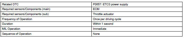
Toyota Sienna Service Manual: Actuator Supply Voltage Circuit / Open

DESCRIPTION
The ECM monitors the output voltage to the throttle actuator. This self-check ensures that the ECM is functioning properly. The output voltage is usually 0 V when the ignition switch is turned off. If the output voltage is higher than 7 volts when the ignition switch is turned off, the ECM will illuminate the MIL and set a DTC when the ignition switch is turned on.

MONITOR STRATEGY
TYPICAL ENABLING CONDITIONS

TYPICAL MALFUNCTION THRESHOLDS

INSPECTION PROCEDURE
1 CHECK WHETHER DTC OUTPUT RECURS (IN ADDITION TO DTC P0657)
(a) Connect the intelligent tester to the DLC3.
(b) Turn the ignition switch to the ON position.
(c) Turn the tester on.
(d) Clear the DTC.
(e) Turn the ignition switch off.
(f) Disconnect the battery negative terminal and wait for 1 minute.
(g) Connect the battery negative terminal.
(h) Turn the ignition switch to the ON position for 10 seconds.
(i) Turn the ignition switch off.
(j) Turn the ignition switch to the ON position.
(k) Enter the following menus: DIAGNOSIS / ENHANCED II / DTC INFO / CURRENT CODES.
(l) Read the DTCs.
Result 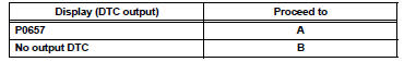

REPLACE ECM
 VIN not Programmed or Mismatch - ECM / PCM
DESCRIPTION
DTC P0630 is set when the Vehicle Identification Number (VIN) is not stored
in the Engine Control Module
(ECM) or the input VIN is not accurate. Input the VIN with the intelligent ...
 Transmission Range Sensor Circuit Malfunction (PRNDL Input)
DESCRIPTION
The park/neutral position switch detects the shift lever position and sends
signals to the ECM.
HINT:
After confirming DTC P0705, use the intelligent tester to confirm the PN ...
Other materials:
Removal
1. REMOVE V-BANK COVER SUB-ASSEMBLY (See
page EM-28)
2. REMOVE NO. 1 ENGINE UNDER COVER (See page
EM-26)
3. DRAIN ENGINE COOLANT (See page CO-6)
4. REMOVE FRONT WHEEL RH
5. REMOVE FRONT FENDER APRON SEAL RH
6. REMOVE V-RIBBED BELT (See page EM-6)
7. DISCONNECT NO. 2 RADIATOR HOSE
(a) Di ...
Power Source Circuit
DESCRIPTION
Power is supplied to the fold seat control ECU through the L-RR2 SEAT and
R-RR2 SEAT fuses.
WIRING DIAGRAM
INSPECTION PROCEDURE
1 INSPECT FUSE (L-RR2 SEAT, R-RR2 SEAT)
Remove the fuses from the R/B No. 3.
Measure the resistance according to the value(s) in the
...
Short in Front Pretensioner Squib RH Circuit
DTC B0130/63 Short in Front Pretensioner Squib RH Circuit
DESCRIPTION
The front pretensioner squib RH circuit consists of the center airbag sensor
assembly and the front seat
outer belt assembly RH.
This circuit instructs the SRS to deploy when deployment conditions are met.
DTC B0130/63 ...
