Toyota Sienna Service Manual: Adjustment
1. ADJUST BUZZER VOLUME
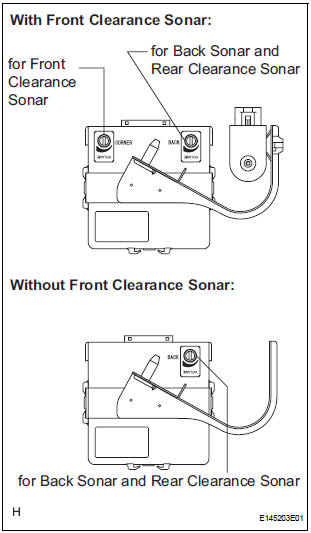
- Turn the knob on the clearance warning ECU to adjust the volume.
- Park / Neutral Position Switch Circuit
- Speed Signal Circuit
- Back Sonar Sensor LH Circuit
- Back Sonar Sensor RH Circuit
- Front Clearance Sonar Sensor LH Circuit
- Front Clearance Sonar Sensor RH Circuit
- Rear Clearance Sonar Sensor LH Circuit
- Rear Clearance Sonar Sensor RH Circuit
- No. 1 Clearance Warning Buzzer Circuit
- Clearance Warning ECU Power Source Circuit
- No. 2 Clearance Warning Buzzer Circuit
- Indicator Circuit
 Terminals of ECU
1. CLEARANCE WARNING ECU
*1: with Front Clearance Sonar
2. AIR CONDITIONER AMPLIFIER ASSEMBLY
*1: with Front Clearance Sonar
*2: Manual A/C
*3: Auto A/C
Reference: ...
 Park / Neutral Position Switch Circuit
DESCRIPTION
The clearance warning ECU receives the reverse or park position signal from
the park / neutral position
switch.
WIRING DIAGRAM
INSPECTION PROCEDURE
1 INSPECT CLEARANCE WARNING E ...
Other materials:
How to proceed with
troubleshooting
HINT:
Troubleshoot in accordance with the procedures on the
following pages
1 VEHICLE BROUGHT TO WORKSHOP
2 CUSTOMER PROBLEM ANALYSIS CHECK AND SYMPTOM CHECK
3 INSPECT COMMUNICATION FUNCTION OF LARGE-SCALE MULTIPLEX
COMMUNICATION SYSTEM (BEAN)
Use the intelligent tester to check for normal ...
Trailer Tongue Weight
A recommended tongue weight varies in accordance with the types
of trailers or towing as described below.
To ensure the recommended values shown below, the trailer must
be loaded by referring to the following instructions.
Tongue Weight
The gross trailer weight should be distribute ...
Hitch
Trailer hitch assemblies have different weight capacities. Toyota recommends
the use of Toyota hitch/bracket for your vehicle. For details,
contact your Toyota dealer.
If you wish to install a trailer hitch, contact your Toyota
dealer.
Use only a hitch that conforms to the gross trailer w ...
