Toyota Sienna Service Manual: Adjustment
HINT: If the malfunction does not disappear by following the procedure in ADJUSTMENT and the rear No. 2 seat assembly needs to be replaced, do not disassemble the rear No. 2 seat assembly.
1. ADJUST FRONT LEG
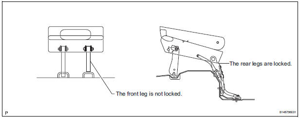
HINT: Perform the following procedure if the inner leg does not lock.
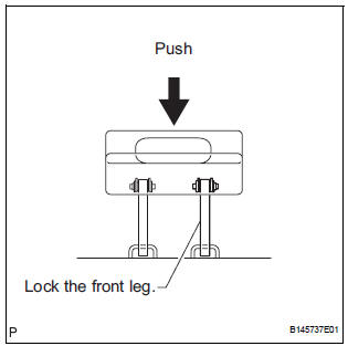
- Push down on the rear No. 2 seat assembly to lock the front leg.
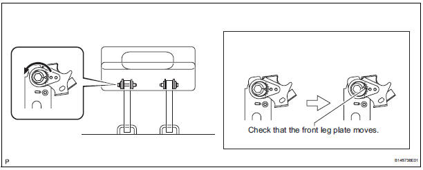
- Loosen the bolt on the front leg that has locked and move the rear No. 2 seat assembly up and down a few times.
NOTICE: Check that the front leg plate moves.
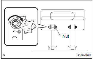
- Tighten the bolt.
Torque: 14.5 N*m (153 kgf*cm, 11 ft.*lbf) NOTICE: Hold the nut to prevent it from turning.
- Check that the rear No. 2 seat assembly operates
normally and both front legs lock securely.
NOTICE: If any of the front legs do not lock, loosen the bolt on the front leg that has not locked, and perform the procedure from (b) again.
2. REINSTALL REAR NO. 2 SEAT ASSEMBLY
HINT: Perform the following procedure if the rear No. 2 seat assembly is removed with any of the 4 legs released or if the rear legs are moved with the rear No. 2 seat assembly removed.
- Remove the following components:
- Rear No. 2 seat leg side garnish sub-assembly
- Rear seat leg garnish sub-assembly
- No. 2 seat hinge cover
- Rear No. 2 seat assembly
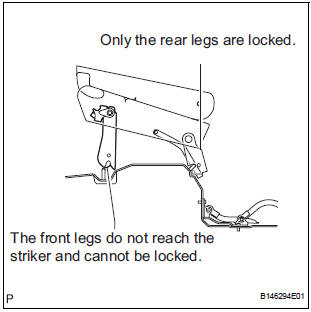
- Lock the rear legs to the striker.
- Lock the front legs to the striker.
- If any of the front legs do not lock, perform the following procedure:
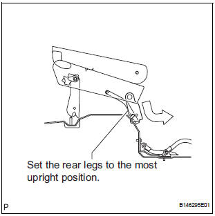
- Connect the connector.
- Operate the stowing/return switch to set the rear legs to the most upright position.
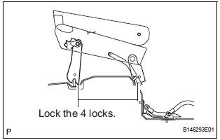
- Lock the front legs to the striker.
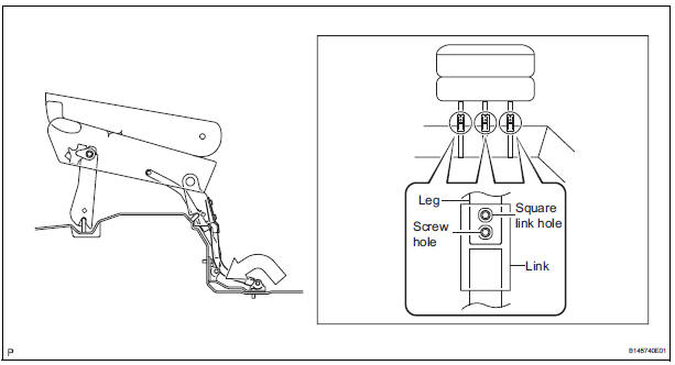
- Align the links of the No. 2 seat leg sub-assembly with the No. 2 seat cushion frame sub-assembly.
- Align the screw holes on the No. 2 cushion frame
sub-assembly with the square link holes on the No.
2 seat leg sub-assembly.
HINT: If the holes do not align, move the No. 2 seat cushion frame sub-assembly horizontally to align the holes.
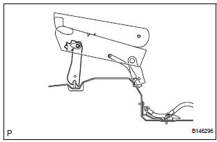
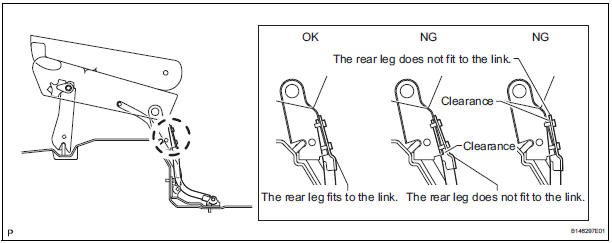
- Operate the stowing/return switch to adjust the rear legs so that the rear legs fit to the links of the No. 2 seat leg sub-assembly as shown in the illustration.
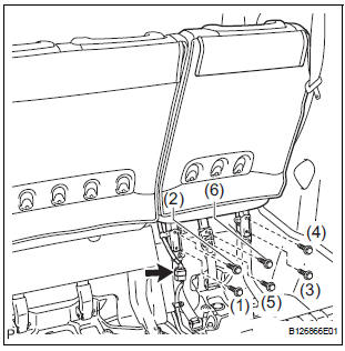
- Install the 6 bolts.
Torque: 19 N*m (194 kgf*cm, 14 ft.*lbf) NOTICE: Tighten the bolts in the order shown in the illustration.
- Install the following components:
- No. 2 seat hinge cover
- Rear seat leg garnish sub-assembly
- Rear No. 2 seat leg side garnish sub-assembly
- Check that the rear No. 2 seat assembly operates normally and the rear legs lock securely.
NOTICE: If any of the front legs do not lock normally, perform the procedure in "1. ADJUST FRONT LEG".
 Disassembly
1. REMOVE REAR NO. 2 SEAT COVER BEZEL
Remove the 3 screws.
Disengage the 3 claws and remove the rear No. 2
seat cover bezel.
2. REMOVE REAR SEAT RECLINING COVER RH
& ...
 Reassembly
1. INSTALL NO. 2 SEAT LEG SUB-ASSEMBLY
Install the No. 2 seat leg sub-assembly with the 3
bolts and nut.
Torque: 19 N*m (194 kgf*cm, 14 ft.*lbf)
NOTICE:
Tighten the bolts and nut ...
Other materials:
Emergency flashers
The emergency flashers are used to warn other drivers when the
vehicle has to be stopped in the road due to a breakdown, etc.
Press the switch.
All the turn signal lights will flash.
To turn them off, press the switch
once again.
Emergency flashers
If the emergency flashers are used f ...
Rear blower resistor
ON-VEHICLE INSPECTION
1. INSPECT REAR BLOWER MOTOR CONTROLLER
(a) Measure resistance according to the value(s) in the
table below..
Standard resistance
If the resistance is not as specified, replace the rear
blower motor controller.
(b) Inspect the rear blower motor controller.
(1 ...
Master cylinder pressure sensor check (when using intelligent tester)
(a) Leave the vehicle in a stationary condition and
release the brake pedal for 1 second or more, and
quickly depress the brake pedal with a force of 98 N
(10 kgf, 22 lbf) or more for 1 second or more.
(b) Check the ABS warning light stays on for 3
seconds
HINT:
Ensure that the ABS warni ...
