Toyota Sienna Service Manual: Air Conditioning Compressor Magnetic Clutch Circuit
DESCRIPTION
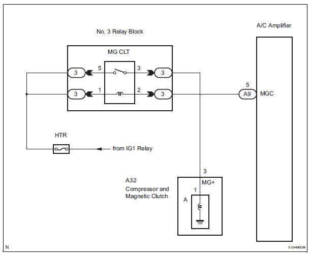
When the A/C amplifier is turned on, a magnetic clutch ON signal is sent from the MGC terminal of the A/ C amplifier. Then, the MG CLT relay turns on to operate the magnetic clutch.
WIRING DIAGRAM
INSPECTION PROCEDURE
1 CHECK CAN COMMUNICATION SYSTEM
(a) Use the intelligent tester to check if the CAN communication system is functioning normally.
Result 

2 CHECK MULTIPLEX COMMUNICATION SYSTEM
(a) Use the intelligent tester to check if the multiplex communication system is functioning normally.
Result 

3 PERFORM ACTIVE TEST BY INTELLIGENT TESTER
(a) Connect the intelligent tester to the DLC3.
(b) Turn the ignition switch to the ON position and turn the intelligent tester main switch on.
(c) Select the item below in the ACTIVE TEST and then check that the relay operates.
ACTIVE TEST / AIR CONDITIONER:
OK: Magnetic clutch relay operates.


PROCEED TO NEXT CIRCUIT INSPECTION SHOWN IN PROBLEM SYMPTOMS TABLE
4 INSPECT FUSE (HTR)
(a) Remove the HTR fuse from the driver side junction block.
(b) Measure the resistance according to the value(s) in the table below.
Standard resistance 
(c) Reconnect the HTR fuse to the driver side junction block.

5 INSPECT RELAY (MG CLT)
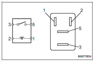
(a) Remove the MG CLT relay from the No. 3 relay block.
(b) Measure the resistance according to the value(s) in the table below.
Standard resistance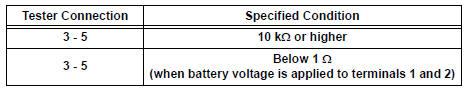
(c) Install the MG CLT relay to the No. 3 relay block.

6 CHECK HARNESS AND CONNECTOR (A/C AMPLIFIER - BATTERY)
(a) Disconnect the connector from the A/C amplifier.
(b) Measure the voltage according to the value(s) in the table below.
Standard voltage 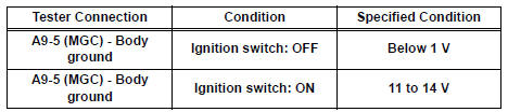

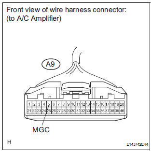
7 INSPECT A/C AMPLIFIER
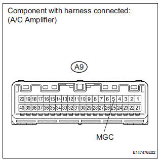
(a) Reconnect the connector to the A/C amplifier.
(b) Measure the voltage according to the value(s) in the table below.
Standard voltage 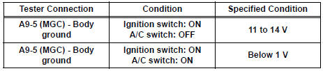

8 INSPECT COMPRESSOR AND MAGNETIC CLUTCH
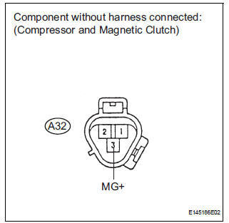
(a) Disconnect the connector from the compressor and magnetic clutch.
(b) Disconnect the connector from the magnetic clutch.
(c) Measure the resistance according to the value(s) in the table below.
Standard resistance 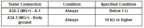

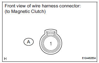
9 INSPECT MAGNETIC CLUTCH
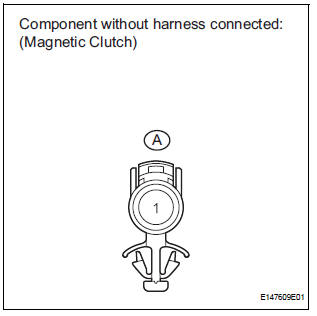
(a) Measure the resistance according to the value(s) in the table below.
Standard resistance 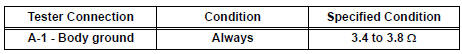
(b) When connector terminal A1 is connected to the positive (+) battery terminal, check that the following occurs: 1) the magnetic clutch's operating sound can be heard, and 2) the magnetic clutch's hub and rotor lock.


10 CHECK HARNESS AND CONNECTOR (NO. 3 RELAY BLOCK - BATTERY)
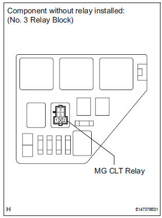
(a) Remove the MG CLT relay from the No. 3 relay block.
(b) Turn the ignition switch to the ON position.
(c) Measure the voltage according to the value(s) in the table below.
Standard voltage 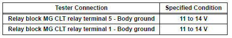

REPAIR OR REPLACE HARNESS OR CONNECTOR
 Blower Motor Circuit
DESCRIPTION
The blower motor is operated by signals from the A/C amplifier. Blower motor
speed signals are
transmitted by changes in the Duty Ratio.
Duty Ratio
The duty ratio is the ratio of ...
 Rear Air Conditioning Control Panel Circuit
DESCRIPTION
This is the rear A/C system control signal circuit as well as the power
supply circuit of the rear A/C control
assembly.
Pulse signals regarding rear A/C control panel switch operat ...
Other materials:
Removal
1. DRAIN POWER STEERING FLUID
2. REMOVE FRONT WHEEL RH
3. REMOVE FRONT FENDER APRON SEAL RH (See
page EM-26)
4. REMOVE FAN AND GENERATOR V BELT (See page
EM-6)
5. DISCONNECT NO. 1 FLUID RESERVOIR TO PUMP HOSE
(a) Slide the clip and disconnect the No. 1 fluid
reservoir to pump hose from t ...
Removal
HINT:
Use the same procedures for the RH side and LH side.
The procedures listed below are for the LH side.
1. PRECAUTION
CAUTION:
Be sure to read "PRECAUTION" thoroughly before
servicing.
2. DISCONNECT CABLE FROM NEGATIVE BATTERY
TERMINAL
CAUTION:
Wait for 90 s ...
Seat Position Airbag Sensor Circuit Malfunction
DTC B1153/25 Seat Position Airbag Sensor Circuit Malfunction
DESCRIPTION
The seat position airbag sensor circuit consists of the center airbag sensor
assembly and the seat
position airbag sensor.
DTC B1153/25 is recorded when a malfunction is detected in the seat position
airbag sensor cir ...
