Toyota Sienna Service Manual: Air Inlet Damper Position Sensor Circuit
DESCRIPTION
This sensor detects the position of the air inlet control servo motor and sends the appropriate signals to the A/C amplifier. The position sensor is built in the air inlet control servo motor.
The position sensor's resistance changes as the air inlet control servo motor arm moves.
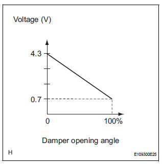
It outputs voltage (5 V) that is input to terminal 1 and terminal 3 via the variable resistor, and then to the A/ C amplifier.
The A/C amplifier determines the arm position based on the input voltage from
the position sensor. 
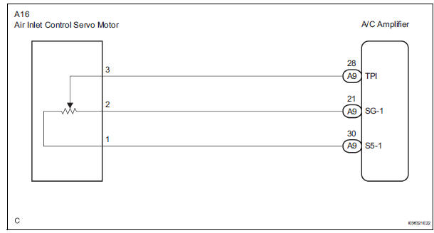
WIRING DIAGRAM
INSPECTION PROCEDURE
1 READ VALUE OF INTELLIGENT TESTER
(a) Connect the intelligent tester to the DLC3.
(b) Turn the ignition switch to the ON position and turn the intelligent tester main switch on.
(c) Select the items below in the DATA LIST, and read the display on the intelligent tester.
DATA LIST / AIR CONDITIONER 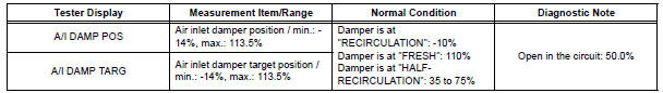
OK: The display is as specified in the normal condition column.
Result 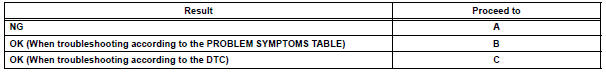

2 INSPECT AIR INLET CONTROL SERVO MOTOR
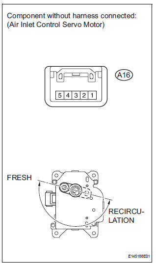
(a) Remove the air inlet control servo motor.
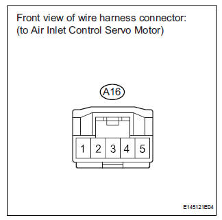
(b) Disconnect the connector from the air inlet control servo motor.
(c) Measure the resistance according to the value(s) in the table below.
Standard resistance 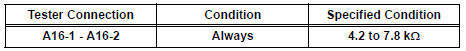
(d) Measure the resistance according to the value(s) in the table below.
Standard resistance 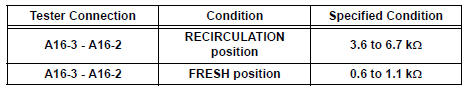
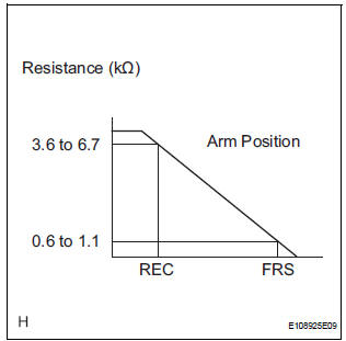
(e) As the air inlet control servo motor moves from RECIRCULATION to FRESH, the resistance decreases gradually without interruption.

3 CHECK HARNESS AND CONNECTOR (AIR INLET CONTROL SERVO MOTOR - A/C AMPLIFIER)
(a) Disconnect the connector from the A/C amplifier.
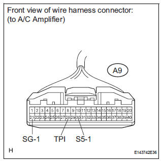
(b) Measure the resistance according to the value(s) in the table below.
Standard resistance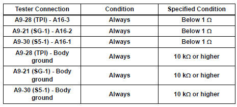

Standard resistance
 Air Mix Damper Position Sensor Circuit (Passenger Side)
DESCRIPTION
This sensor detects the position of the air mix control servo motor (air mix
damper) and sends the
appropriate signals to the A/C amplifier. The position sensor is built in the
a ...
 Air Outlet Damper Position Sensor Circuit
DESCRIPTION
This sensor detects the position of the air outlet control servo motor and
sends the appropriate signals to
the A/C amplifier. The position sensor is built in the air outlet contro ...
Other materials:
Diagnosis system
1. CHECK DLC3
The ECU uses ISO 15765-4 for communication.
The terminal arrangement of the DLC3 complies
with SAE J1962 and meets the ISO 15765-4 format.
NOTICE:
*: Before measuring the resistance, leave the
vehicle as is for at least 1 minute and do not
operate the ignition s ...
On-vehicle inspection
1. Check battery electrolyte level
(a) Check the electrolyte level.
(1) If the electrolyte level is low, replace the battery
(or add distilled water) and check the charging
system.
2. CHECK BATTERY SPECIFIC GRAVITY
(a) Check the color of the hydrometer.
Result
3. CHECK BATTERY VOLTAGE ...
Disassembly
1. INSPECT OIL PUMP ASSEMBLY
HINT:
(See page AX-234)
2. REMOVE CLUTCH DRUM OIL SEAL RING
(a) Remove the 2 clutch drum oil seal rings.
3. REMOVE STATOR SHAFT ASSEMBLY
(a) Using a "torx" socket (T30), remove the 11 bolts and
stator shaft.
4. INSPECT CLEARANCE OF OIL PUMP ASSEMBLY ...
