Toyota Sienna Service Manual: Air Mix Damper Control Servo Motor Circuit (Driver Side)
DESCRIPTION
The air mix control servo motor (air mix damper servo sub-assembly) is controlled by the A/C amplifier.
The air mix control servo motor moves the air mix damper by rotating (normal, reverse) with electrical power from the A/C amplifier.
This adjusts the mix ratio of the air that passes through the evaporator and heater core and controls the air flow temperature. Air flow temperature changes when moving the air mix damper to the target point.
The target point can be detected by the air mix damper position sensor.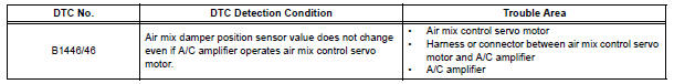
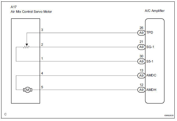
WIRING DIAGRAM
INSPECTION PROCEDURE
1 READ VALUE OF INTELLIGENT TESTER
(a) Connect the intelligent tester to the DLC3.
(b) Turn the ignition switch to the ON position and turn the intelligent tester main switch on.
(c) Select the items below in the DATA LIST, and read the display on the intelligent tester.
DATA LIST / AIR CONDITIONER
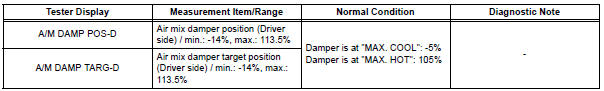
OK: When the target position is "MAX. COOL" (-5%), the actual opening angle is 19.0% or less.
When the target position is "MAX. HOT" (105%), the actual opening angle is 81.0% or more.
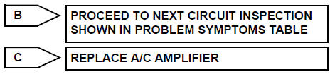
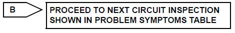
Result 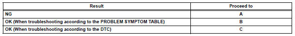

2 PERFORM ACTIVE TEST BY INTELLIGENT TESTER
(a) Connect the intelligent tester to the DLC3.
(b) Turn the ignition switch to the ON position and turn the intelligent tester main switch on.
(c) Select the item below in the ACTIVE TEST and then check the air flow temperature by hand.
ACTIVE TEST / AIR CONDITIONER 
OK: When the lever is moved to the "MAX. HOT" side, warm air comes out.
When the lever is moved to the "MAX. COOL" side, cool air comes out.
Result 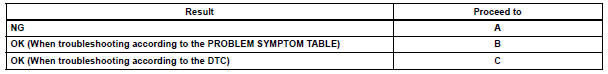

3 PERFORM ACTUATOR CHECK
(a) Enter the actuator check mode (See page AC-15).
(b) Press the DEF switch and change to the step operation.
(c) Check the air flow temperature by hand.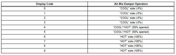
OK: Air flow temperature changes in accordance with each display code.
Result 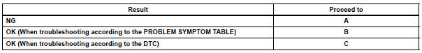

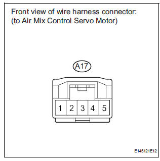
4 INSPECT AIR MIX CONTROL SERVO MOTOR
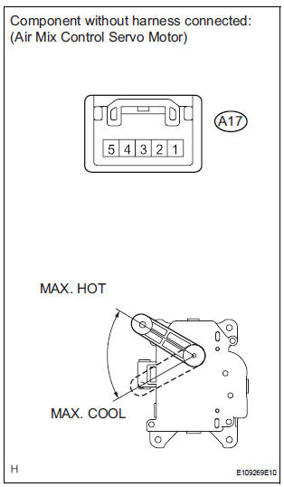
(a) Remove the air mix control servo motor.
(b) Disconnect the connector from the air mix control servo motor.
(c) Connect the positive (+) lead from the battery to terminal 5 and the negative (-) lead to terminal 4, then check that the lever turns to the "MAX. HOT" position smoothly.
OK: Lever turns to "MAX. HOT" position smoothly.
(d) Connect the positive (+) lead from the battery to terminal 4 and the negative (-) lead to terminal 5, then check that the lever turns to the "MAX. COOL" position smoothly.
OK: Lever turns to "MAX. COOL" position smoothly.

5 CHECK HARNESS AND CONNECTOR (AIR MIX CONTROL SERVO MOTOR - A/C AMPLIFIER)
(a) Disconnect the connector from the A/C amplifier.
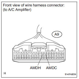
(b) Measure the resistance according to the value(s) in the table below.
Standard resistance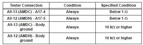

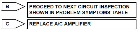
REPLACE A/C AMPLIFIER
 Air Outlet Damper Control Servo Motor Circuit
DESCRIPTION
This circuit turns the servo motor and changes each damper position by
receiving the signals from the A/
C amplifier.
The air outlet damper servo motor switches the air outlet mode ...
 Rear Air Mix Damper Control Servo Motor Circuit
DESCRIPTION
The rear air mix control servo motor (water valve servo motor) is controlled
by the A/C amplifier.
The rear air mix control servo motor moves the air mix damper by rotating
(normal ...
Other materials:
CAN Bus Line
DESCRIPTION
When any DTC for the CAN communication system is output, first measure the
resistance between the
terminals of the DLC3 to specify the trouble area, and check that there is no
short in the CAN main wire,
between the main wire, and +B or GND.
WIRING DIAGRAM
INSPECTION PRO ...
Adjustment
CAUTION:
Do not stare at the luminous portion of the laser
during adjustment. The intensity of the laser light is
low, but it may result in loss of sight.
If operation is not carried out as specified, there may
be a risk that you are exposed to hazardous radiation.
HINT:
...
Checking and replacing
fuses
If any of the electrical components do not operate, a fuse may
have blown. If this happens, check and replace the fuses as necessary.
Turn the engine switch to the “LOCK” position (vehicles without a
smart key system) or off (vehicles with a smart key system).
Open the fuse box cover.
...
