Toyota Sienna Service Manual: Air Mix Damper Position Sensor Circuit (Driver Side)
DESCRIPTION
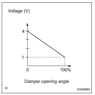
This sensor detects the position of the air mix control servo motor (air outlet damper) and sends the appropriate signals to the A/C amplifier. The position sensor is built in the air mix control servo motor. The position sensor resistance changes as the air mix control servo motor arm moves.
It outputs voltage (5 V) that is input to terminal 1 and terminal 3 via the
variable resistor, and then to the A/
C amplifier. The A/C amplifier determines the arm position based on the input
voltage from the position
sensor.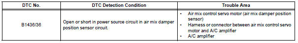
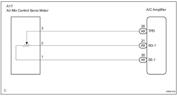
WIRING DIAGRAM
INSPECTION PROCEDURE
1 READ VALUE OF INTELLIGENT TESTER
(a) Connect the intelligent tester to the DLC3.
(b) Turn the ignition switch to the ON position and turn the intelligent tester main switch on.
(c) Select the items below in the DATA LIST, and read the display on the intelligent tester.
DATA LIST / AIR CONDITIONER 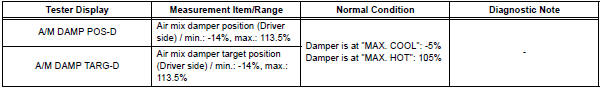
OK: The display is as specified in the normal condition column.
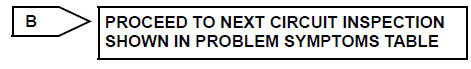
Result 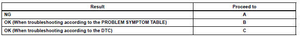
2 INSPECT AIR MIX CONTROL SERVO MOTOR
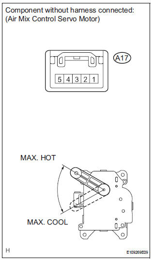
(a) Remove the air mix control servo motor.
(b) Disconnect the connector from the air mix control servo motor.
(c) Measure the resistance according to the value(s) in the table below.
Standard resistance 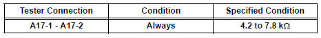
(d) Measure the resistance according to the value(s) in the table below.
Standard resistance 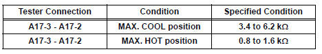
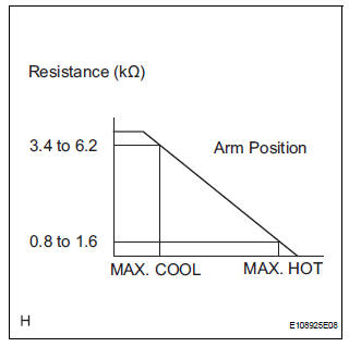
(e) As the air mix control servo motor moves from the COOL side to the HOT side, the resistance decreases gradually without interruption.

3 CHECK HARNESS AND CONNECTOR (AIR MIX CONTROL SERVO MOTOR - A/C AMPLIFIER)
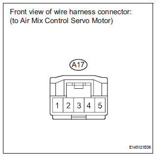
(a) Disconnect the connector from the A/C amplifier.
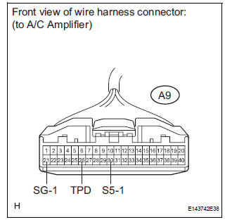
(b) Measure the resistance according to the value(s) in the table below.
Standard resistance 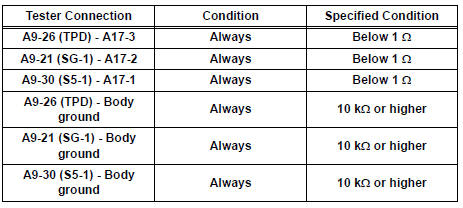

REPLACE A/C AMPLIFIER
 Air Outlet Damper Position Sensor Circuit
DESCRIPTION
This sensor detects the position of the air outlet control servo motor and
sends the appropriate signals to
the A/C amplifier. The position sensor is built in the air outlet contro ...
 Rear Air Mix Damper Position Sensor Circuit
DESCRIPTION
This sensor detects the position of the rear air mix control servo motor
(water valve servo motor) and
sends the appropriate signals to the A/C amplifier. The position sensor is bu ...
Other materials:
System description
1. GENERAL
To assist the driver with parking the vehicle by
displaying an image of the area behind the vehicle,
this system has a television camera mounted on the
luggage compartment door. The system displays
the image on the radio and navigation assembly.
This system consi ...
Master Error
DTC 01-DF Master Error
DESCRIPTION
DTC No.
DTC Detection Condition
Trouble Area
01-DF
*1
The device with a display fails and the master is
switched to the audio device.
Also when a communication error between sub-master
(audio) and master occu ...
Cruise Control Switch Circuit
DESCRIPTION
The cruise control main switch operates 8 functions: SET, - (COAST),
TAP-DOWN, RES (RESUME), +
(ACCEL), TAP-UP, CANCEL, and MODE. The SET, TAP-DOWN, and - (COAST) functions,
and the RES
(RESUME), TAP-UP, and + (ACCEL) functions are operated with the same switch. The
cruise contr ...
