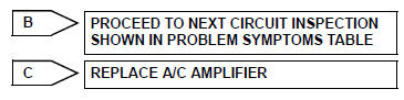
Toyota Sienna Service Manual: Air Outlet Damper Control Servo Motor Circuit
DESCRIPTION
This circuit turns the servo motor and changes each damper position by receiving the signals from the A/ C amplifier.
The air outlet damper servo motor switches the air outlet mode by rotating (normal, reverse) with electrical power from the A/C amplifier.
When the AUTO switch is on, the A/C amplifier changes the mode between "FACE",
"FACE/FOOT" and
"FOOT" according to the temperature setting.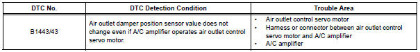
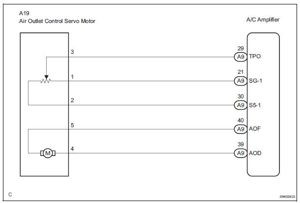
WIRING DIAGRAM
INSPECTION PROCEDURE
1 READ VALUE OF INTELLIGENT TESTER
(a) Connect the intelligent tester to the DLC3.
(b) Turn the ignition switch to the ON position and turn the intelligent tester main switch on.
(c) Select the items below in the DATA LIST, and read the display on the intelligent tester.
DATA LIST / AIR CONDITIONER 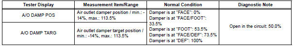
OK: When the target position is "FACE" (0%), the actual opening angle is 19.0% or less.
When the target position is "DEF" (100%), the actual opening angle is 81.0% or more.
Result 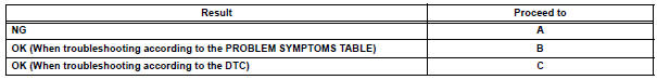

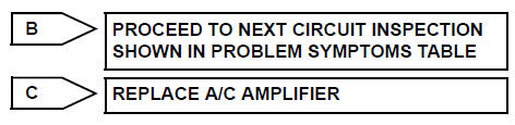
2 PERFORM ACTIVE TEST BY INTELLIGENT TESTER
(a) Connect the intelligent tester to the DLC3.
(b) Turn the ignition switch to the ON position and turn the intelligent tester main switch on.
(c) Select the item below in the ACTIVE TEST and then check that the air flow position by hand.
ACTIVE TEST / AIR CONDITIONER 
OK: Air comes out from the selected air outlet.
Result 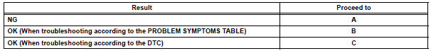

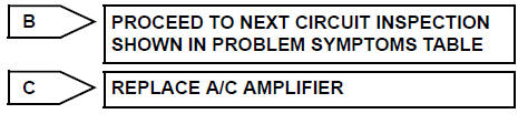
3 PERFORM ACTUATOR CHECK
(a) Warm up the engine.
(b) Enter the actuator check mode (See page AC-15).
(c) Press the DEF switch and change to step operation.
(d) Press the DEF switch and check the air flow by hand.
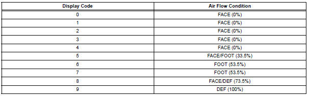
OK: Air outlet mode changes in accordance with each display code.
Result 

4 INSPECT AIR OUTLET CONTROL SERVO MOTOR
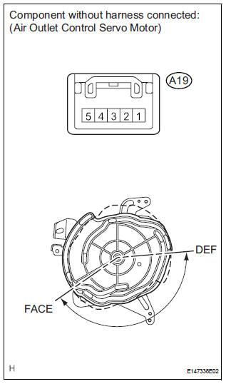
(a) Remove the air outlet control servo motor.
(b) Disconnect the connector from the air outlet control servo motor.
(c) Connect the positive (+) lead from the battery to terminal 4 and the negative (-) lead to terminal 5, then check that the lever turns to the "DEF" position smoothly.
OK: Lever turns to "DEF" position smoothly.
(d) Connect the positive (+) lead from the battery to terminal 5 and the negative (-) lead to terminal 4, then check that the lever turn to the "FACE" position smoothly.
OK: Lever turns to "FACE" position smoothly.


5 CHECK HARNESS AND CONNECTOR (AIR OUTLET CONTROL SERVO MOTOR - A/C AMPLIFIER)
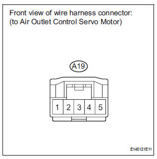
(a) Disconnect the connector from the A/C amplifier.
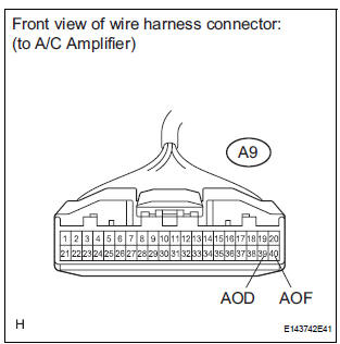
(b) Measure the resistance according to the value(s) in the table below.
Standard resistance 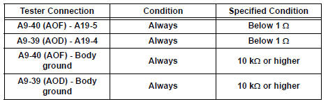

REPLACE A/C AMPLIFIER
 Air Inlet Damper Control Servo Motor Circuit
DESCRIPTION
The air inlet control servo motor is controlled by the A/C amplifier and
moved to the desired position.
The air inlet control servo motor switches the air inlet mode by rotating
(n ...
 Air Mix Damper Control Servo Motor Circuit (Driver Side)
DESCRIPTION
The air mix control servo motor (air mix damper servo sub-assembly) is
controlled by the A/C amplifier.
The air mix control servo motor moves the air mix damper by rotating (normal, ...
Other materials:
Reassembly
1. INSTALL PARKING BRAKE SWITCH ASSEMBLY
(a) Install the parking brake switch to the parking brake
pedal with the screw.
2. INSTALL PARKING BRAKE CABLE ASSEMBLY NO.1
(a) Connect the parking brake cable No. 1 to the
parking brake cable equalizer.
(b) Install the parking brake cable No. 1 with ...
Installation
1. REMOVE FRONT SEAT INNER BELT ASSEMBLY
HINT:
Refer to the instructions for reassembly of the front seat assembly
(for flat type).
Refer to the instructions for reassembly of the front seat assembly
(for manual seat).
Refer to the instructions for reassembly of the ...
DTC check / clear
1. CHECK DTC
Connect the intelligent tester to the DLC3.
Connect the intelligent tester to the Controller
Area Network Vehicle Interface Module (CAN
VIM). Then connect the CAN VIM to the Data
Link Connector 3 (DLC3).
Turn the ignition switch to the ON posi ...
