Toyota Sienna Service Manual: All Doors cannot be Locked / Unlocked at Once
DESCRIPTION
The body ECU receives a switch signal from the master switch, the door control switch, the driver door key cylinder and the passenger door key cylinder and then drives the door lock motor.
WIRING DIAGRAM
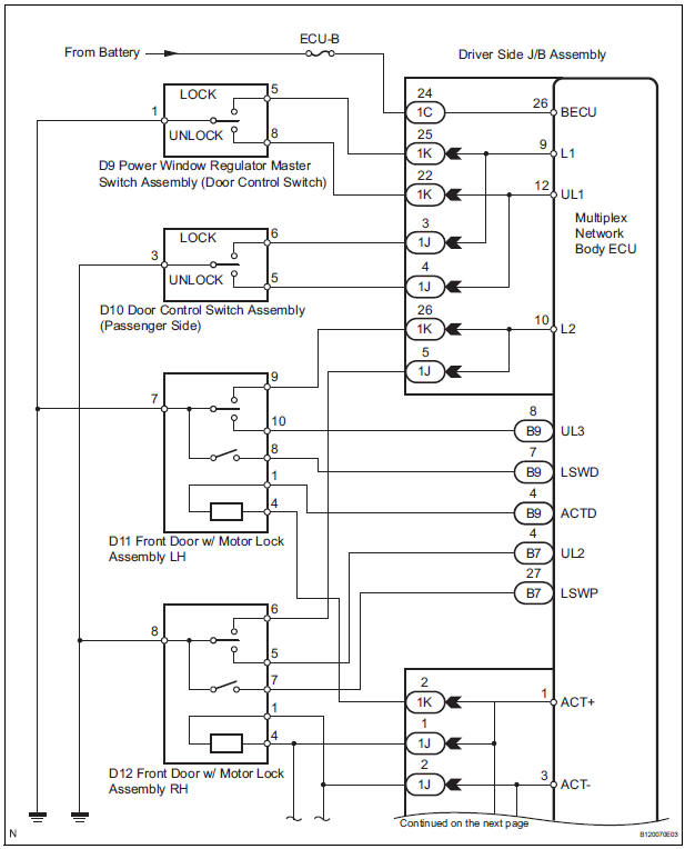
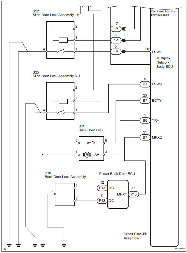
INSPECTION PROCEDURE
1 INSPECT FUSE (ECU-B)
- Remove ECU-B fuse from engine room junction block.
- Measure the resistance.
Standard resistance: Below 1 Ω
2 PERFORM ACTIVE TEST BY INTELLIGENT TESTER
- Select the ACTIVE TEST and then check that the power door lock operates.
HINT: During the ACTIVE TEST, the intelligent tester sends a signal to the body ECU to drive all the power door lock motors. If the power door lock operates, the power door lock motor itself and the wire harness between the power door lock motor and body ECU are considered to be functioning normally.
BODY (Multiplex network body ECU)

3 CHECK OPERATION (MASTER SWITCH OR KEY CYLINDER)
- When manual door lock/unlock operation via the master switch can not be performed, proceed to A.
- When manual door lock/unlock operation via the door control switch (passenger side) can not be performed, proceed to B.
- When manual door lock/unlock operation interlocked with the driver side door lock key cylinder can not be performed, proceed to C.
- When manual door lock/unlock operation interlocked with the passenger side door lock key cylinder can not be performed, proceed to D.
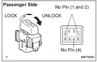
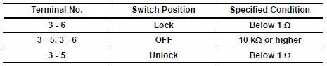
4 INSPECT POWER WINDOW REGULATOR SWITCH ASSEMBLY (DOOR CONTROL SWITCH)
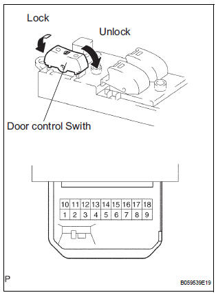
- Remove the master switch.
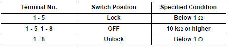
- Measure the resistance according to the value(s) in the table below.
Standard resistance
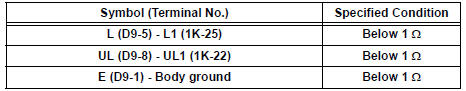
5 CHECK HARNESS AND CONNECTOR (POWER WINDOW REGULATOR MASTER SWITCH - DRIVER SIDE J/B)
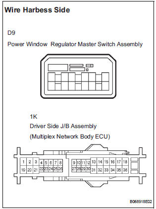
- Disconnect the D9 switch and 1K J/B connectors.
- Measure the resistance according to the value(s) in the table below.
Standard resistance
REPAIR OR REPLACE HARNESS OR CONNECTOR
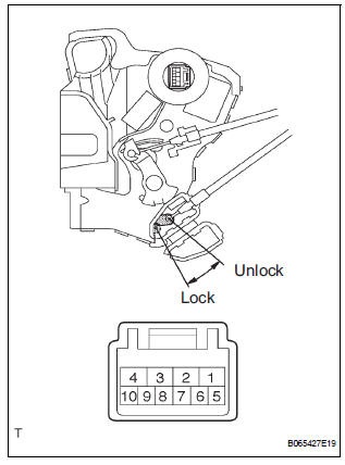
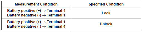
6 INSPECT DOOR CONTROL SWITCH ASSEMBLY
- Passenger side: Inspect the resistance of the switch.
Standard resistance
7 CHECK HARNESS AND CONNECTOR (DOOR CONTROL SWITCH (PASSENGER SIDE) -DRIVER SIDE J/B)
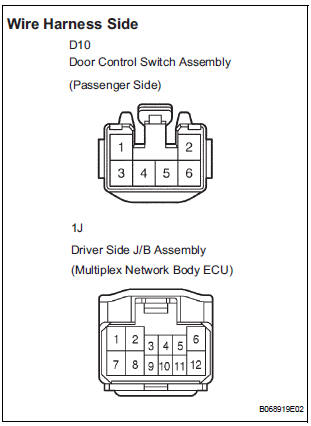
- Disconnect the D10 switch and 1J J/B connectors.
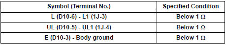
- Measure the resistance according to the value(s) in the table below.
Standard resistance
REPAIR OR REPLACE HARNESS OR CONNECTOR
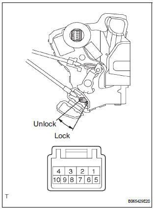
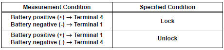
8 INSPECT FRONT DOOR W/ MOTOR LOCK ASSEMBLY LH
- Apply battery voltage and inspect operation of the door lock motor.
Standard
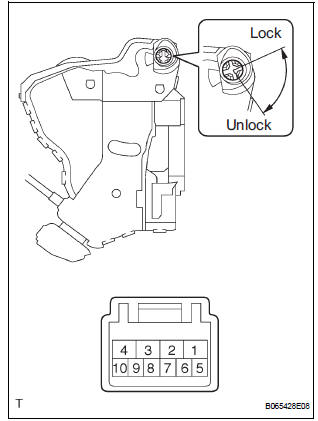
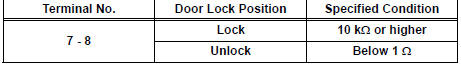
- Inspect the resistance of the door lock and unlock switch.
Standard resistance
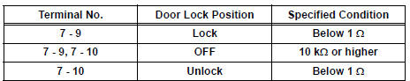
- Inspect the resistance of the position switch.
Standard resistance
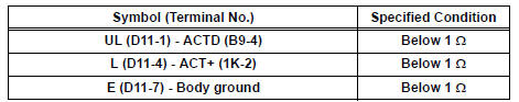
9 CHECK HARNESS AND CONNECTOR (FRONT DOOR W/ MOTOR LOCK ASSEMBLY - DRIVER SIDE J/B)
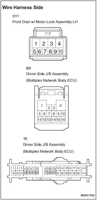
- Disconnect the D11 door lock, B9 and 1K body ECU connectors.
- Measure the resistance according to the value(s) in the table below.
Standard resistance
REPLACE DRIVER SIDE JUNCTION BLOCK ASSEMBLY (MULTIPLEX NETWORK BODY ECU)
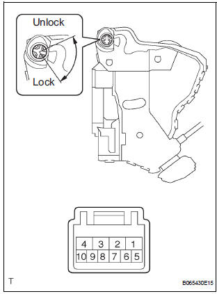
10 INSPECT FRONT DOOR W/MOTOR LOCK ASSEMBLY RH
- Apply battery voltage and inspect operation of the door lock motor.
Standard
- Inspect the resistance of the door lock and unlock switch.
Standard resistance
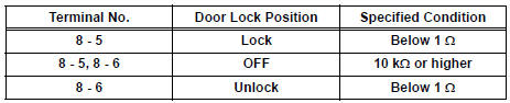
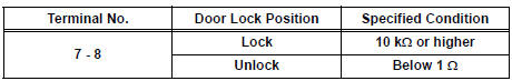
- Inspect the resistance of the position switch.
Standard resistance
11 CHECK HARNESS AND CONNECTOR (FRONT DOOR W/ MOTOR LOCK ASSEMBLY RH - DRIVER SIDE J/B)
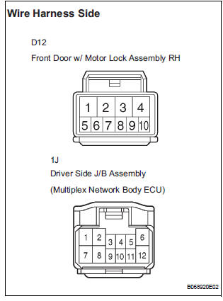
- Disconnect the D12 door lock and 1J body ECU connectors.
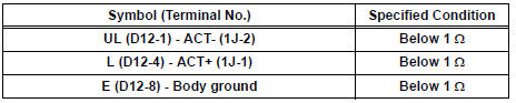
- Measure the resistance according to the value(s) in the table below.
Standard resistance
REPLACE DRIVER SIDE JUNCTION BLOCK ASSEMBLY (MULTIPLEX NETWORK BODY ECU)
 Data list / active test
1. READ DATA LIST
HINT:
Using the intelligent tester's DATA LIST allows switch,
actuator and other item values to be read without
removing any parts. Reading the DATA LIST early in
troubleshootin ...
 Key Lock-in Prevention Function does not Work Properly (Manual
Operation and Operation Interlocked with Key are Active)
Key Lock-in Prevention Function does not Work Properly (Manual
Operation and Operation Interlocked with Key are Active)
DESCRIPTION
The un-lock warning switch turns ON when the key is inserted in the ignition
key cylinder. The courtesy
light switch turns ON when the driver side door is opened. These 2 switches are ...
Other materials:
Taking out the spare tire
Slide the front passenger’s seat to the frontmost lock position and
the right side second seat to the rearmost lock position so they will
not interfere with the jack handle.
Open the right side sliding door
and you will find the flap on the
floor. Pull back the flap to find
the ...
Push Switch / Key Unlock Warning Switch Malfunction
DTC B2780 Push Switch / Key Unlock Warning Switch Malfunction
DESCRIPTION
This DTC will be output if the transponder key ECU does not detect that the
unlock warning switch is on
even when the ignition switch is on (Under the normal conditions, the unlock
warning switch is on when
the ignitio ...
Installation
1. INSTALL COMBINATION METER ASSEMBLY
Connect the connectors.
Install the combination meter assembly with the 4
screws.
2. INSTALL INSTRUMENT CLUSTER FINISH PANEL SUB-ASSEMBLY
Install the instrument cluster finish panel subassembly
with the 4 clips.
3. C ...
