Toyota Sienna Service Manual: Antenna Coil Open / Short
DTC B2784 Antenna Coil Open / Short
DESCRIPTION
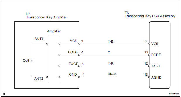
The transponder key coil is built into the transponder key amplifier and receives a key code signal from the transponder chip in the key. This signal is amplified by the amplifier, and output to the transponder key ECU.
|
DTC No. |
DTC Detection Condition |
Trouble Area |
|
B2784 |
Antenna coil open/short |
|
WIRING DIAGRAM
INSPECTION PROCEDURE
1 READ VALUE OF INTELLIGENT TESTER
- Connect the intelligent tester (with CAN VIM) to the DLC3.
- Turn the ignition switch on and turn the intelligent tester main switch on.
- Select ANTENNA COIL in the DATA LIST and read the value displayed on the intelligent tester.
Transponder key ECU:
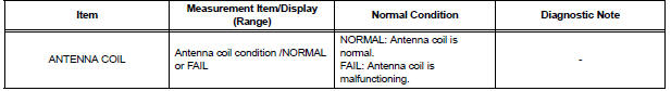
OK: NORMAL (Antenna coil is normal) appears on the screen.
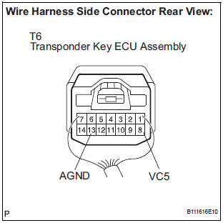
2 CHECK HARNESS AND CONNECTOR (TRANSPONDER KEY ECU ASSEMBLY -TRANSPONDER KEY AMPLIFIER)
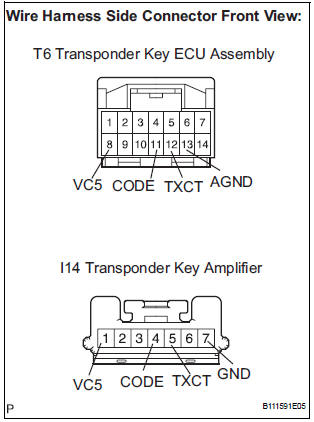
- Disconnect the T6 ECU and I14 switch connectors.
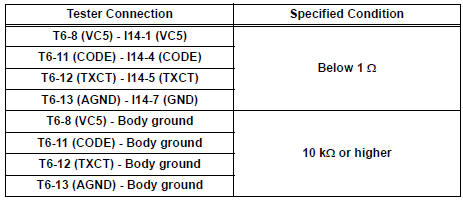
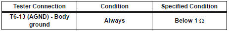
- Measure the resistance according to the value(s) in the table below.
Resistance
3 INSPECT TRANSPONDER KEY ECU ASSEMBLY
- Reconnect the T6 ECU and I14 amplifier connectors.
- Measure the voltage according to the value(s) in the table below.
Voltage

- Measure the resistance according to the value(s) in the table below.
Resistance
REPLACE TRANSPONDER KEY AMPLIFIER
 Push Switch / Key Unlock Warning Switch Malfunction
DTC B2780 Push Switch / Key Unlock Warning Switch Malfunction
DESCRIPTION
This DTC will be output if the transponder key ECU does not detect that the
unlock warning switch is on
even when the ign ...
 Transponder Chip Malfunction
DTC B2793 Transponder Chip Malfunction
DESCRIPTION
This DTC is output when a malfunction is found in the key during the key code
registration or the key code
is not registered normally. Replace t ...
Other materials:
Television Display Power Source Circuit
DESCRIPTION
This is the power source circuit to operate the television display assembly.
WIRING DIAGRAM
INSPECTION PROCEDURE
1 INSPECT TELEVISION DISPLAY ASSEMBLY
Disconnect the connector from the television display
assembly.
Measure the resistance according to the value(s) ...
Audio system types
Entune Audio
Entune Audio Plus/Entune Premium Audio with Navigation
Owners of models equipped with a navigation system should refer to
the “NAVIGATION AND MULTIMEDIA SYSTEM OWNER’S
MANUAL”.
Using cellular phones
Interference may be heard through the audio system’s speakers if a c ...
Player Error
DTC 58-44 Player Error
DTC 80-44 Player Error
DESCRIPTION
DTC No.
DTC Detection Condition
Trouble Area
58-44
Map player error is detected
Radio and navigation assembly
80-44
Map player error is detected.
INSPECTION PROCEDURE
HINT: ...
