Toyota Sienna Service Manual: Automatic Light Control Sensor Circuit
DESCRIPTION
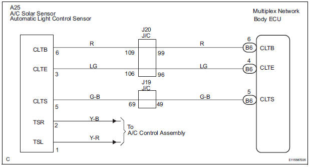
The Multiplex network body ECU receives the signal from the automatic light control sensor.
HINT: DTC code is output when malfunction of automatic light control sensor or open or short of automatic light control sensor circuit occurs.
WIRING DIAGRAM
INSPECTION PROCEDURE
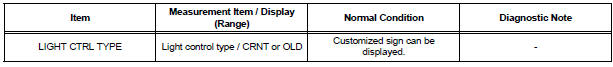
1 READ VALUE OF INTELLIGENT TESTER
- Connect the intelligent tester to DLC3.
- Turn the ignition switch ON and push the intelligent tester main switch ON.
- Select the items below in the DATA LIST, and read the displays on the intelligent tester
BODY NO.1:
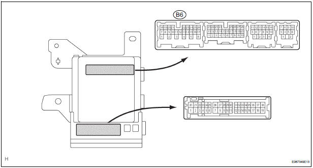
2 CHECK HARNESS AND CONNECTOR (MULTIPLEX NETWORK BODY ECU - AUTOMATIC LIGHT CONTROL SENSOR)
- Check for open or short circuit in the harness and the connector between the terminal 6 of the automatic light control sensor and the terminal B6-6 of the multiplex network body ECU.
- Check for open or short circuit in the harness and the connector between the terminal 3 of the automatic light control sensor and the terminal B6-4 of the multiplex network body ECU.
- Check for open or short circuit in the harness and the connector between the terminal 5 of the automatic light control sensor and the terminal B6-5 of the multiplex network body ECU
3 INSPECT INSTRUMENT PANEL JUNCTION BLOCK ASSEMBLY
- Measure voltage between the terminal B6-4 and the terminal B6-6 of the multiplex network body ECU in the instrument panel junction block assembly.
Voltage

PROCEED TO NEXT CIRCUIT INSPECTION SHOWN IN PROBLEM SYMPTOMS TABLE
 Light Control Switch Circuit
DESCRIPTION
This circuit detects the state of the headlight dimmer switch.
WIRING DIAGRAM
INSPECTION PROCEDURE
1 READ VALUE OF INTELLIGENT TESTER
Connect the intelligent tester to DLC3.
...
 Door Courtesy Switch Circuit
DESCRIPTION
The Multiplex network body ECU detects the condition of the door courtesy
switch assembly.
WIRING DIAGRAM
INSPECTION PROCEDURE
1 READ VALUE OF INTELLIGENT TESTER
Connect the ...
Other materials:
Cooling fan relay
On-vehicle inspection
1. Cooling fan relay
(a) Remove the relay from engine room relay block No.
1.
(b) Measure the resistance of the relay.
Standard resistance
If the result is not as specified, replace the cooling
fan relay.
(c) Install the relay to engine room relay block No. ...
Removal
1. REMOVE INSTRUMENT CLUSTER CENTER NO. 1 FINISH PANEL
2. REMOVE INSTRUMENT CLUSTER CENTER NO. 2
FINISH PANEL
3. REMOVE SHIFT LEVER KNOB SUB-ASSEMBLY
4. REMOVE POSITION INDICATOR HOUSING ASSEMBLY
5. REMOVE INSTRUMENT CLUSTER CENTER LOWER FINISH PANEL SUB-ASSEMBLY
6. REMOVE CIGARETTE LIGHTER CO ...
Evaporative Emission Control System Leak Detected
DTC SUMMARY
DESCRIPTION
The circuit description can be found in the EVAP (Evaporative Emission)
System (See page ES-409).
INSPECTION PROCEDURE
Refer to the EVAP System (See page ES-412).
MONITOR DESCRIPTION
5 hours*1 after the ignition switch is turned off, the electric vacuum pump
c ...
