Toyota Sienna Service Manual: AVC-LAN Circuit
DESCRIPTION
Each unit of the audio system connected to the AVC-LAN (communication bus) transfers the signal of each switch by communication.
When a short to +B or short to ground occurs in this AVC-LAN, the audio system will not function normally as the communication is discontinued.
INSPECTION PROCEDURE
1 INSPECT RADIO RECEIVER
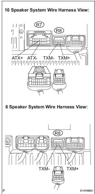
- Disconnect the radio receiver connectors.
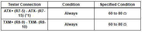
- Measure the resistance according to the value(s) in the table below.
Standard resistance
*1: 10 Speaker System
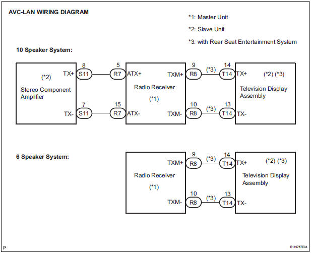
2 CHECK HARNESS AND CONNECTOR
HINT: For details of the connectors, refer to the "TERMINALS OF ECU"
- Referring to the AVC-LAN wiring diagram below, check all AVC-LAN circuits.
- Disconnect all connectors in all AVC-LAN circuits.
- Check for an open or short in all AVC-LAN circuits.
OK: There is no open or short circuit
PROCEED TO NEXT CIRCUIT INSPECTION SHOWN IN PROBLEM SYMPTOMS TABLE
 Mute Signal Circuit between Radio Receiver and Television Display
Assembly
Mute Signal Circuit between Radio Receiver and Television Display
Assembly
DESCRIPTION
The radio receiver controls the volume according to the MUTE signal from the
television display
assembly.
The MUTE signal is sent to reduce noise and a popping sound generated when ...
 Vehicle Speed Signal Circuit between Multi-display and Combination
Meter
Vehicle Speed Signal Circuit between Multi-display and Combination
Meter
DESCRIPTION
This circuit is necessary for the ASL (Auto Sound Leveliser) built into the
radio receiver.
Speed signals are received from the combination meter and used for the ASL.
The ASL fun ...
Other materials:
Map Disc Read Error
DTC 58-42 Map Disc Read Error
DTC 80-42 Map Disc Read Error
DESCRIPTION
DTC No.
DTC Detection Condition
Trouble Area
58-42
Player error
Scratches or dirt on the disc
Access to an invalid address due to software error
...
TC and CG Terminal Circuit
DESCRIPTION
Connecting terminals TC and CG of the DLC3 causes the ECU to display the DTC
by blinking the ABS
warning light and/or VSC warning light.
WIRING DIAGRAM
INSPECTION PROCEDURE
NOTICE:
When replacing the brake actuator assembly, perform zero point calibration
(See page BC-70).
...
Reassembly
1. INSTALL TRANSFER DRIVEN PINION REAR BEARING
(a) Using SST(s) and a press, install the transfer driven
pinion rear bearing outer race to the transfer case.
SST 09950-60010 (09951-00620), 09950-70010
(09951-07150)
NOTICE:
Place something like wood blocks under the
case to keep its level. ...
