Toyota Sienna Service Manual: Back-up Power Source Circuit
DESCRIPTION
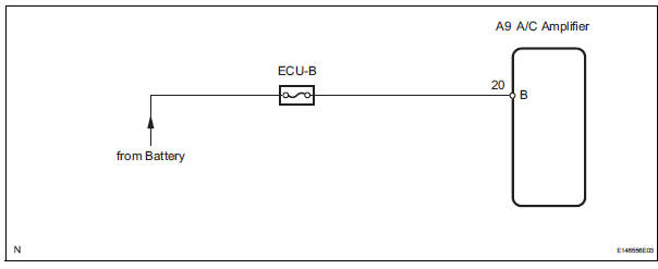
This is the back-up power source for the A/C amplifier. Power is supplied even when the ignition switch is off and is used for diagnostic trouble code memory, etc.
WIRING DIAGRAM
INSPECTION PROCEDURE
1 INSPECT FUSE (ECU-B)
(a) Remove the ECU-B fuse from the engine room junction block.
(b) Measure the resistance according to the value(s) in the table below.
Standard resistance


2 CHECK HARNESS AND CONNECTOR (A/C AMPLIFIER - BATTERY)
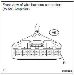
(a) Disconnect the connector from the A/C amplifier.
(b) Measure the voltage according to the value(s) in the table below.
Standard voltage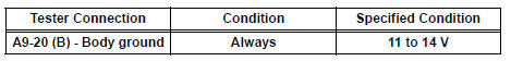


PROCEED TO NEXT CIRCUIT INSPECTION SHOWN IN PROBLEM SYMPTOMS TABLE
 ACC Power Source Circuit
DESCRIPTION
This circuit supplies power to the A/C amplifier and the illumination for the
clock.
WIRING DIAGRAM
INSPECTION PROCEDURE
1 INSPECT FUSE (ECU ACC)
(a) Remove the ECU ACC fuse fr ...

Other materials:
Short in Driver Side Squib Circuit
DTC B0100/13 Short in Driver Side Squib Circuit
DESCRIPTION
The driver side squib circuit consists of the center airbag sensor assembly,
the spiral cable and the
steering pad. The circuit instructs the SRS to deploy when deployment conditions
are met. DTC B0100/13
is recorded when a short ci ...
Vehicle Speed Signal Circuit between Radio Receiver and Combination
Meter
DESCRIPTION
This circuit is necessary for the ASL (Auto Sound Leveliser) built into the
radio receiver.
Speed signals are received from the combination meter and used for the ASL.
The ASL function automatically adjusts the sound data in order to enable hearing
the clear audio sound
even ...
Driving position memory
Your preferred driving position (the position of the driverŌĆÖs seat and
outside rear view mirrors) can be recalled by pressing a button.
Two different driving positions can be recorded into memory.
Recording procedure
Check that the shift lever is in P.
Turn the engine switch to IGNI ...
