Toyota Sienna Service Manual: Blower Motor Circuit
DESCRIPTION
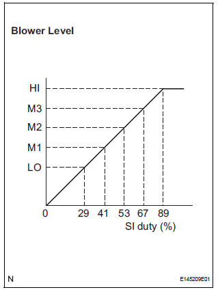
The blower motor is operated by signals from the A/C amplifier. Blower motor speed signals are transmitted by changes in the Duty Ratio.
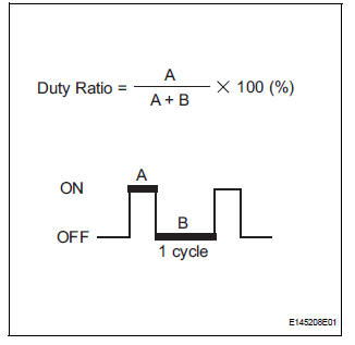
Duty Ratio
The duty ratio is the ratio of the period of continuity in one cycle. For example, if A is the period of continuity in one cycle, and B is the period of non-continuity, then Duty Ratio = A/(A+B) x 100 (%).
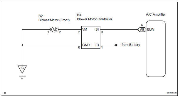
WIRING DIAGRAM
INSPECTION PROCEDURE
1 READ VALUE OF INTELLIGENT TESTER
(a) Connect the intelligent tester to the DLC3.
(b) Turn the ignition switch to the ON position and turn the intelligent tester main switch on.
(c) Select the item below in the DATA LIST, and read the display on the intelligent tester.
DATA LIST / AIR CONDITIONER 
OK: The display is as specified in the normal condition column.


PROCEED TO NEXT CIRCUIT INSPECTION SHOWN IN PROBLEM SYMPTOMS TABLE
2 PERFORM ACTIVE TEST BY INTELLIGENT TESTER
(a) Connect the intelligent tester to the DLC3.
(b) Turn the ignition switch to the ON position and turn the intelligent tester main switch on.
(c) Select the item below in the ACTIVE TEST and then check that the blower motor operates.
ACTIVE TEST / AIR CONDITIONER 
OK: The blower motor operates and the blower level changes.


PROCEED TO NEXT CIRCUIT INSPECTION SHOWN IN PROBLEM SYMPTOMS TABLE
3 PERFORM ACTUATOR CHECK
(a) Enter the actuator check mode (See page AC-15).
(b) Press the DEF switch to change to the step operation.
(c) Check the air flow level by hand.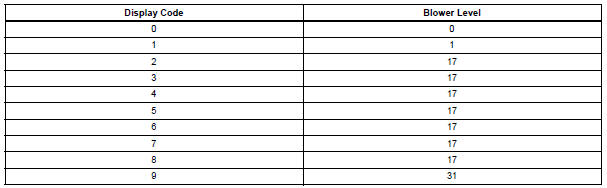
OK: The blower level changes in accordance with each display code.


PROCEED TO NEXT CIRCUIT INSPECTION SHOWN IN PROBLEM SYMPTOMS TABLE
4 INSPECT BLOWER MOTOR
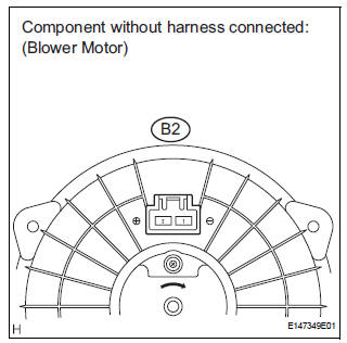
(a) Remove the blower motor.
(b) Disconnect the connector from the blower motor.
(c) Connect the positive (+) lead from the battery to terminal 2 and the negative (-) lead to terminal 1, and check that the motor operates.
OK: Blower motor operates smoothly.


5 CHECK HARNESS AND CONNECTOR (BLOWER MOTOR - BLOWER MOTOR CONTROLLER)
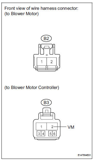
(a) Disconnect the connector from the blower motor.
(b) Disconnect the connector from the blower motor controller.
(c) Measure the resistance according to the value(s) in the table below.
Standard resistance 


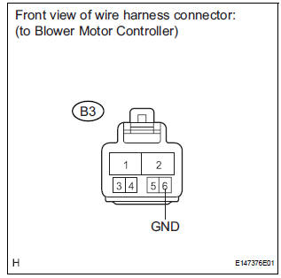
6 CHECK HARNESS AND CONNECTOR (BLOWER MOTOR - BODY GROUND)
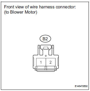
(a) Measure the resistance according to the value(s) in the table below.
Standard resistance 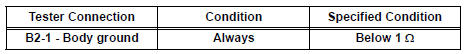

7 CHECK HARNESS AND CONNECTOR (BLOWER MOTOR CONTROLLER - BODY GROUND)
(a) Measure the resistance according to the value(s) in the table below.
Standard resistance 

8 CHECK HARNESS AND CONNECTOR (BLOWER MOTOR CONTROLLER - BATTERY)
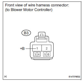
(a) Measure the voltage according to the value(s) in the table below.
Standard voltage 

9 CHECK HARNESS AND CONNECTOR (A/C AMPLIFIER - BLOWER MOTOR CONTROLLER)
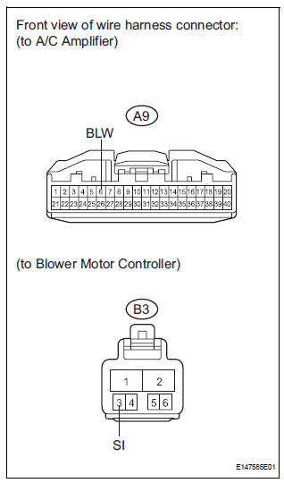
(a) Disconnect the connector from the A/C amplifier.
(b) Measure the resistance according to the value(s) in the table below.
Standard resistance 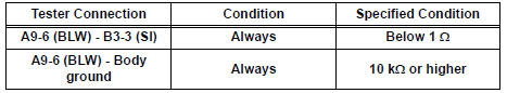


10 INSPECT A/C AMPLIFIER
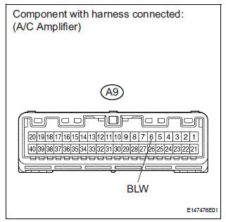
(a) Reconnect the connector to the A/C amplifier.
(b) Reconnect the connector to the blower motor controller.
(c) Reconnect the connector to the blower motor
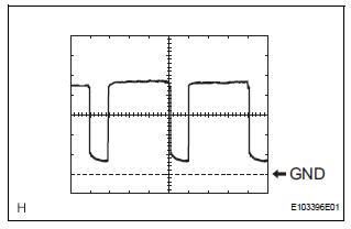
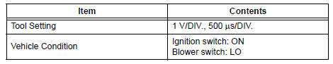
(d) Measure the waveform between terminal A9-6 (BLW) of the A/C amplifier and body ground.
OK: Waveform is as shown in the illustration.
HINT:
Waveform varies with the blower level.

REPLACE BLOWER MOTOR CONTROLLER
 Multiplex Communication Circuit
DESCRIPTION
INSPECTION PROCEDURE
1 GO TO CAN COMMUNICATION SYSTEM
(a) Refer to the CAN communication system (See page CA-
7).
(b) If the CAN communication system is operating normally,
procee ...
 Air Conditioning Compressor Magnetic Clutch Circuit
DESCRIPTION
When the A/C amplifier is turned on, a magnetic clutch ON signal is sent from
the MGC terminal of the A/
C amplifier. Then, the MG CLT relay turns on to operate the magnetic clutch.
W ...
Other materials:
Selecting trailer ball
Use the correct trailer ball for your application.
Trailer ball load rating
Matches or exceeds the gross
trailer weight rating of the trailer.
Ball diameter
Matches the size of the trailer coupler.
Most couplers are stamped
with the required trailer ball size.
Shank len ...
Short to B+ in CAN Bus Line
DESCRIPTION
A short to B+ is suspected in the CAN bus wire when the resistance between
terminals 6 (CANH) and 16
(BAT), or terminals 14 (CANL) and 16 (BAT) of the DLC3 is below 6 kΩ.
Symptom
Trouble Area
The resistance between terminals 6 (CANH) and 16 (BAT), or
...
System Voltage
DTC P0560 System Voltage
MONITOR DESCRIPTION
The battery supplies electricity to the ECM even when the ignition switch is
off. This power allows the
ECM to store data such as DTC history, freeze frame data and fuel trim values.
If the battery voltage falls
below a minimum level, these memori ...
