Toyota Sienna Service Manual: Brake Switch
DESCRIPTION
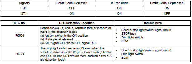
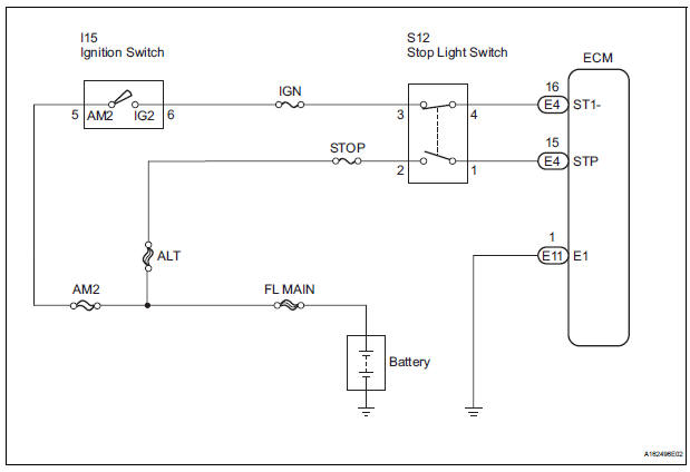
The stop light switch is a duplex system that transmits two signals: STP and ST1-. These two signals are used by the ECM to monitor whether or not the brake system is working properly. If the signals, which indicate the brake pedal is being depressed or released, are detected simultaneously, the ECM interprets this as a malfunction in the stop light switch and sets the DTC.
HINT:
The normal conditions are as shown in the table below. The signals can be read using the intelligent tester.
MONITOR DESCRIPTION
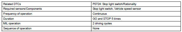
This DTC indicates that the stop light switch remains on. When the stop light switch remains ON during "stop and go" driving, the ECM interprets this as a fault in the stop light switch and the MIL comes on and the ECM stores the DTC. The vehicle must stop (less than 2 mph (3 km/h)) and go (19 mph (30 km/h) or more) 5 times for two driving cycles in order to detect a malfunction.
MONITOR STRATEGY
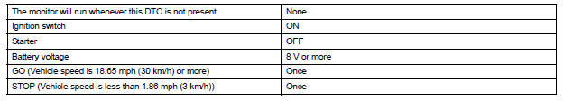
TYPICAL ENABLING CONDITIONS
TYPICAL MALFUNCTION THRESHOLDS

WIRING DIAGRAM
INSPECTION PROCEDURE
HINT:
Read freeze frame data using the intelligent tester. The ECM records vehicle and driving condition information as freeze frame data the moment a DTC is stored. When troubleshooting, freeze frame data can be helpful in determining whether the vehicle was running or stopped, whether the engine was warmed up or not, whether the air-fuel ratio was lean or rich, as well as other data recorded at the time of a malfunction.
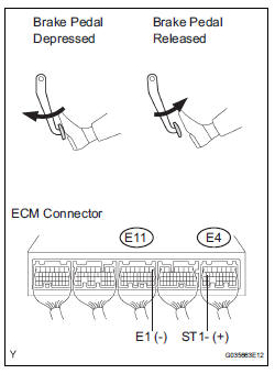
1 CHECK OPERATION OF STOP LIGHT
(a) Check whether the stop lights turn on and off normally when the brake pedal is depressed and released.
OK: Stop lights turn on when brake pedal is depressed.

2 INSPECT STOP LIGHT SWITCH ASSEMBLY
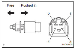
(a) Remove the S12 stop light switch assembly.
(b) Measure the resistance according to the value(s) in the table below.
Standard resistance 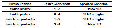
(c) Reinstall the stop light switch assembly


3 READ VALUE OF INTELLIGENT TESTER (STP SIGNAL AND ST1 - VOLTAGE)
(a) Connect the intelligent tester to the DLC3.
(b) Turn the ignition switch to the ON position and turn the tester on.
(c) Select the following menu items: DIAGNOSIS / ENHANCED OBD II / DATA LIST / PRIMARY / STOP LIGHT SW.
(d) Check the STP signal when the brake pedal is depressed and released.
Standard 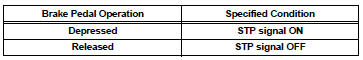
(e) Measure the voltage according to the value(s) in the table below.
Standard voltage 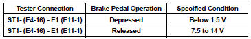


4 CHECK HARNESS AND CONNECTOR (STOP LIGHT SWITCH - ECM)
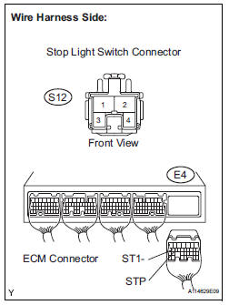
(a) Disconnect the S12 stop light switch connector.
(b) Disconnect the E4 ECM connector.
(c) Measure the resistance according to the value(s) in the table below.
Standard resistance : 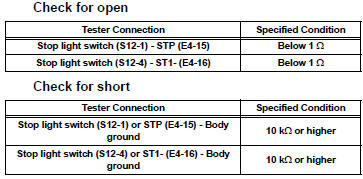
(d) Reconnect the stop light switch connector.
(e) Reconnect the ECM connector.

REPLACE ECM (See page ES-498)
 Vehicle Speed Sensor "A"
DESCRIPTION
The speed sensor detects the wheel speed and sends the appropriate signals to
the skid control ECU.
The skid control ECU converts these wheel speed signals into a 4-pulse signal ...
 Idle Control System Malfunction
DESCRIPTION
The idling speed is controlled by the ETCS (Electronic Throttle Control
System). The ETCS is comprised
of: 1) the one valve type throttle body; 2) the throttle actuator, which
op ...
Other materials:
Center Airbag Sensor Assembly Communication
Circuit Malfunction
DTC B1790 Center Airbag Sensor Assembly Communication
Circuit Malfunction
DESCRIPTION
The center airbag sensor assembly communication circuit consists of the
occupant classification ECU and
the center airbag sensor assembly.
DTC B1790 is recorded when a malfunction is detected in the center ...
Jam Protection Function Activates During Power Back Door Operation
DESCRIPTION
It may be caused by ill-fitting back door, faulty touch sensor or
faulty pulse sensor.
The power back door ECU activates the back motor to open / close
the power back door, thus
controlling the power back door operation. For jam and foreign object
detection, the power ba ...
Summary of functions
Dynamic radar cruise control supplements conventional cruise control
with a vehicle-to-vehicle distance control. In vehicle-to-vehicle distance
control mode, the vehicle automatically accelerates or decelerates
in order to maintain a set following distance from vehicles ahead.
Multi-infor ...
