Toyota Sienna Service Manual: Brake Switch "A" Circuit
DTC P0571 Brake Switch "A" Circuit
DESCRIPTION
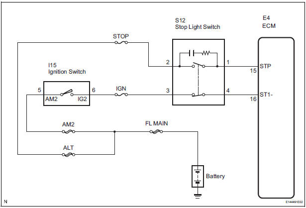
When the brake pedal is depressed, the stop light switch sends a signal to the ECM. When the ECM receives this signal, it cancels the cruise control. The fail-safe function operates to enable normal driving even if there is a malfunction in the stop light signal circuit. The cancellation condition occurs when voltage is applied to terminal STP. When the brake is applied, voltage is normally applied to terminal STP of the ECM through the STOP SW fuse and the stop light switch, and the ECM turns the cruise control off.
|
DTC No. |
DTC Detection Condition |
Trouble Area |
|
P0571 |
Voltage of STP terminal and that of ST1- terminal of ECM are less than 1 V for 0.5 sec. or more |
|
WIRING DIAGRAM
INSPECTION PROCEDURE
1 READ VALUE OF INTELLIGENT TESTER
- Connect the intelligent tester to the DLC3.
- Turn the ignition switch to the ON position, and turn the intelligent tester main switch on.
- Check the DATA LIST for proper functioning of the stop light switch.
ECM (Cruise control):

OK: When the brake pedal is operated, the display changes as shown above.
REPLACE ECM
2 CHECK HARNESS AND CONNECTOR (STOP LIGHT SWITCH - BATTERY)
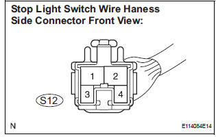
- Disconnect the S12 stop light switch connector.
- Measure the voltage according to the value(s) in the table below.
Standard voltage
3 INSPECT STOP LIGHT SWITCH

- Remove the stop light switch.
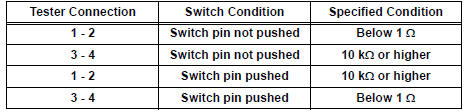
- Measure the resistance according to the value(s) in the table below.
Standard resistance
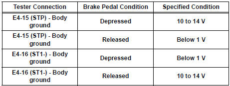
4 CHECK ECM

- Reconnect the S12 stop light switch connector.
- Disconnect the E4 connector from the ECM.
- Turn the ignition switch to the ON position.
- Measure the voltage according to the value(s) in the table below.
Standard voltage
REPLACE ECM
 Vehicle Speed Sensor Malfunction
DTC P0500 Vehicle Speed Sensor Malfunction
DTC P0503 Vehicle Speed Sensor "A" Intermittent / Erratic /
High
DESCRIPTION
The cruise control system uses the same vehicle speed signal that ...
 Stop Light Switch Circuit Malfunction
DTC P0571 Stop Light Switch Circuit Malfunction
DESCRIPTION
The ECM receives the brake demand signal from the distance control ECU and
transmits it to the skid
control ECU (brake actuator assembl ...
Other materials:
Short in Rear Curtain Shield Squib RH Circuit
DTC B1630/83 Short in Rear Curtain Shield Squib RH Circuit
DESCRIPTION
The rear curtain shield squib RH circuit consists of the center airbag sensor
assembly and the curtain
shield airbag assembly RH.
The circuit instructs the SRS to deploy when deployment conditions are met.
DTC B1630/83 ...
How to proceed with
troubleshooting
HINT:
Use this procedure to troubleshoot the engine immobiliser
system.
The intelligent tester should be used in steps 4, 5 and 7.
1 VEHICLE BROUGHT TO WORKSHOP
2 CUSTOMER PROBLEM ANALYSIS CHECK AND SYMPTOM CHECK
3 CRANK ENGINE FOR MORE THAN 10 SECONDS
4 CHECK FOR DTC
C ...
Identification information
VEHICLE IDENTIFICATION AND SERIAL NUMBERS
1. VEHICLE IDENTIFICATION NUMBER
(a) The vehicle identification number is stamped on the
vehicle identification number plate and the
certification label, as shown in the illustration.
A:
Vehicle Identification Number Plate
B:
...
