Toyota Sienna Service Manual: Brake Warning Light does not Come ON
WIRING DIAGRAM
See page BC-52.
INSPECTION PROCEDURE
1 INSPECT BRAKE WARNING LIGHT
(a) Disconnect the skid control ECU connector.
(b) Turn the ignition switch to the on position.
(c) Check that the BRAKE warning light comes on.
OK: BRAKE warning light comes on.
HINT: If troubleshooting has been carried out according to the PROBLEM SYMPTOMS TABLE, refer back to the table and proceed to the next step before replacing the part (See page BC-7).

REPLACE BRAKE ACTUATOR ASSEMBLY
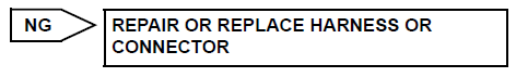
2 CHECK HARNESS AND CONNECTOR (BETWEEN SKID CONTROL ECU AND COMBINATION METER ASSEMBLY)
(a) Turn the ignition switch off.
(b) Disconnect the combination meter connector.
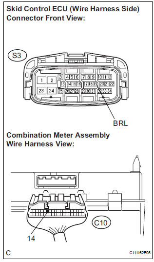
(c) Measure the resistance according to the value(s) in the table below.
Standard resistance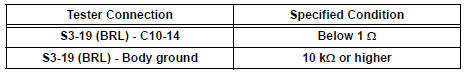

3 INSPECT COMBINATION METER ASSEMBLY
(a) Check the combination meter assembly (See page ME- 4).
HINT: If troubleshooting has been carried out according to the PROBLEM SYMPTOMS TABLE, refer back to the table and proceed to the next step before replacing the part (See page BC-7).

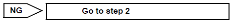
END
 Brake Warning Light Remains ON
DESCRIPTION
If the ECU detects a trouble, it turns on the brake warning light at the same
time of prohibiting ABS
control.
At this time, the ECU records a DTC in memory.
Connect terminals TC ...
 TC and CG Terminal Circuit
DESCRIPTION
DTC output mode is set by connecting terminals TC and CG of the DLC3.
The DTCs are displayed by the blinking pattern of the ABS warning light.
WIRING DIAGRAM
HINT:
When warning ...
Other materials:
Map Disc Read Error
DTC 58-42 Map Disc Read Error
DTC 80-42 Map Disc Read Error
DESCRIPTION
DTC No.
DTC Detection Condition
Trouble Area
58-42
Player error
Scratches or dirt on the disc
Access to an invalid address due to software error
...
Front No. 2 speaker
COMPONENTS
ON-VEHICLE INSPECTION
1. INSPECT FRONT NO.2 SPEAKER
HINT:
Remove interior parts so that the front No.2 speaker can
be seen.
Check the speaker installation.
OK:
The speaker is securely installed.
If the result is not as specified, reinstall the front
No.2 speak ...
On-vehicle inspection
1. FRONT SEAT SIDE AIRBAG ASSEMBLY (VEHICLE NOT INVOLVED IN COLLISION)
Perform a diagnostic system check.
With the front seat side airbag assembly installed on
the vehicle, perform a visual check. If there are any
defects as mentioned below, replace the front
seatback ass ...
