Toyota Sienna Service Manual: Brake Warning Light Remains ON
DESCRIPTION
The BRAKE warning light comes on when the brake fluid is insufficient, the parking brake is applied or the EBD is defective.
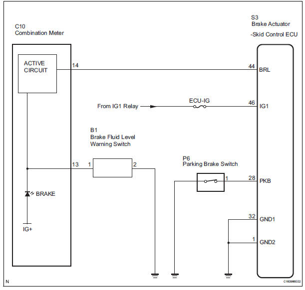
WIRING DIAGRAM
INSPECTION PROCEDURE
HINT: When releasing the parking brake, move the shift lever into the P position in an AT vehicle, and choke in an MT vehicle to hold the vehicle for safety.
1 CHECK BRAKE FLUID LEVEL
(a) Check that the brake fluid level is proper.

2 CHECK DTC
(a) Are the DTC recorded? (See page BC-82)
Result 

REPAIR CIRCUITS INDICATED BY OUTPUT DTCS
3 CHECK BRAKE WARNING LIGHT
ABS / VSC: 
(a) WHEN USING INTELLIGENT TESTER: (1) Connect the intelligent tester to the DLC3.
(2) Start the engine.
(3) Select the item "BRAKE WARN LIGHT" in the ACTIVE TEST and operate the BRAKE warning light on the intelligent tester.
(4) Check that "ON" and "OFF" of the BRAKE warning light are indicated on the combination meter when using the intelligent tester.
OK: Turn the BRAKE warning light on or off in accordance with the intelligent tester.
(b) WHEN NOT USING INTELLIGENT TESTER: (1) Turn the ignition switch off and disconnect the connector from the skid control ECU.
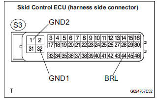
(2) Ground terminal BRL of the skid control ECU.
(3) Turn the ignition switch to the ON position.
(4) Check that the brake warning light.
OK: Turn the light on or off in accordance with the connection of terminal GND and BRL.
NOTICE: When replacing the brake actuator assembly, perform zero point calibration (See page BC-70).

REPLACE BRAKE ACTUATOR ASSEMBLY
4 INSPECT PARKING BRAKE SWITCH
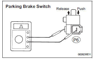
(a) Remove the parking brake switch connector.
(b) Measure the resistance according to the value(s) in the table below.
Standard resistance 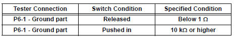

5 CHECK HARNESS AND CONNECTOR (SKID CONTROL ECU - PARKING BRAKE SWITCH)
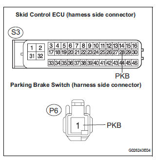
(a) Disconnect the skid control ECU connector and the parking brake switch connector.
(b) Measure the resistance according to the value(s) in the table below.
Standard resistance 
(c) Measure the resistance according to the value(s) in the table below.
Standard resistance 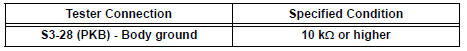
6 INSPECT BRAKE FLUID LEVEL WARNING SWITCH
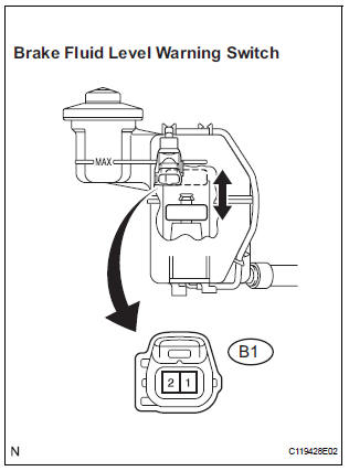
(a) Remove the reservoir tank cap and strainer.
(b) Disconnect the brake fluid level warning switch connector.
(c) Measure the resistance according to the value(s) in the table below.
Standard resistance 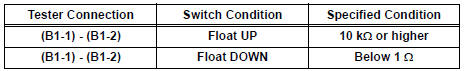

7 CHECK HARNESS AND CONNECTOR (BRAKE FLUID LEVEL WARNING SWITCH - COMBINATION METER)
(a) Disconnect the combination meter connector and the brake fluid level warning switch connector.
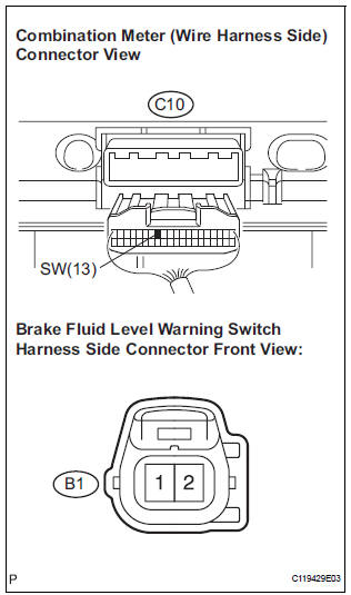
(b) Measure the resistance according to the value(s) in the table below.
Standard resistance 
(c) Measure the resistance according to the value(s) in the table below.
Standard resistance 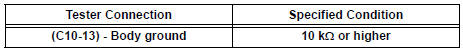

REPAIR OR REPLACE COMBINATION METER ASSEMBLY
 VSC Warning Light does not Come ON
DESCRIPTION
The skid control ECU is connected to the combination meter via CAN and
multiplex communications.
If the skid control ECU stores DTCs to shut down TRAC and VSC operation, the VSC
wa ...
 TRAC OFF Indicator Light Remains ON
DESCRIPTION
The skid control ECU is connected to the combination meter via CAN and
multiplex communications.
When the traction OFF switch is turned on, the TRAC OFF indicator light will
come o ...
Other materials:
Adjustment
1. VEHICLE PREPARATION FOR HEADLIGHT AIMING
ADJUSTMENT
Prepare the vehicle:
Ensure there is no damage or deformation to the
body around the headlights.
Fill the fuel tank.
Make sure that the oil is filled to the specified
level.
Make sure that the c ...
Short in Rear Curtain Shield Squib RH Circuit
DTC B1630/83 Short in Rear Curtain Shield Squib RH Circuit
DESCRIPTION
The rear curtain shield squib RH circuit consists of the center airbag sensor
assembly and the curtain
shield airbag assembly RH.
The circuit instructs the SRS to deploy when deployment conditions are met.
DTC B1630/83 ...
Installation
1. INSTALL ENGINE OIL COOLER
(a) Clean the oil cooler contact surface on the cooler
mounting.
(b) Install a new O-ring to the oil cooler.
(c) Install the oil cooler assembly with the union bolt.
Torque: 68 N*m (693 kgf*cm, 50 ft.*lbf)
Install the 2 water by-pass hoses with the bolt ...
