Toyota Sienna Service Manual: Camshaft Position "A" Actuator Circuit
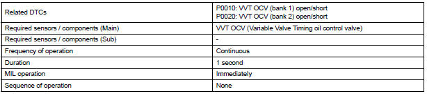
DTC P0010 Camshaft Position "A" Actuator Circuit (Bank 1)
DTC P0020 Camshaft Position "A" Actuator Circuit (Bank 2)
DESCRIPTION
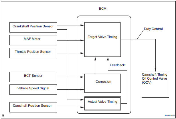
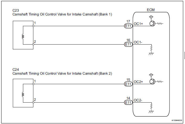
The Variable Valve Timing (VVT) system includes the ECM, Oil Control Valve (OCV) and VVT controller.
The ECM sends a target duty-cycle control signal to the OCV. This control signal regulates the oil pressure supplied to the VVT controller. Camshaft timing control is performed according to engine operating conditions such as intake air volume, throttle valve position and engine coolant temperature.
The ECM controls the OCV, based on the signals transmitted by several sensors. The VVT controller regulates the intake camshaft angle using oil pressure through the OCV. As a result, the relative positions of the camshaft and crankshaft are optimized, the engine torque and fuel economy improves, and the exhaust emissions decrease under overall driving conditions. The ECM detects the actual intake valve timing using signals from the camshaft and crankshaft position sensors, and performs feedback control.
This is how the target intake valve timing is verified by the ECM.
|
DTC No. |
DTC Detection Condition |
Trouble Area |
| P0010 | Open or short in OCV for intake camshaft (bank 1) circuit (1 trip detection logic) |
|
| P0020 | Open or short in OCV for intake camshaft (bank 2) circuit (1 trip detection logic) |
|
MONITOR DESCRIPTION
After the ECM sends the "target" duty-cycle signal to the OCV, the ECM monitors the OCV current to establish an "actual" duty-cycle. The ECM detects a malfunction and sets a DTC when the actual dutycycle ratio varies from the target duty-cycle ratio.
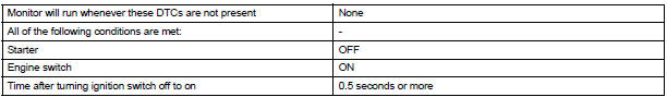
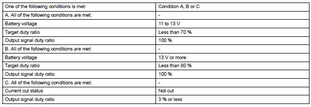
MONITOR STRATEGY
TYPICAL ENABLING CONDITIONS
TYPICAL MALFUNCTION THRESHOLDS
COMPONENT OPERATING RANGE

WIRING DIAGRAM
INSPECTION PROCEDURE
HINT:
- If DTC P0010 is displayed, check the intake camshaft circuit for the right bank VVT system.
- Bank 1 refers to the bank that includes cylinder No. 1.
- If DTC P0020 is displayed, check the intake camshaft circuit for the left bank VVT system.
- Bank 2 refers to the bank that does not include cylinder No. 1.
- Read freeze frame data using the intelligent tester. The ECM records vehicle and driving condition information as freeze frame data the moment a DTC is stored. When troubleshooting, freeze frame data can be helpful in determining whether the vehicle was running or stopped, whether the engine was warmed up or not, whether the air-fuel ratio was lean or rich, as well as other data recorded at the time of a malfunction.
1 PERFORM ACTIVE TEST BY CAMSHAFT TIMING OIL CONTROL VALVE ASSEMBLY (OCV)
- Connect the intelligent tester to the DLC3.
- Start the engine and turn the tester on.
- Warm up the engine.
- On the tester, enter the following menus: DIAGNOSIS / ENHANCED OBD II / ACTIVE TEST / VVT CTRL B1 or VVT CTRL B2.
- Check the engine speed while operating the Oil Control Valve (OCV) using the tester
OK

2 INSPECT CAMSHAFT TIMING OIL CONTROL VALVE ASSEMBLY
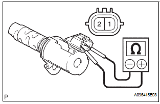
- Disconnect the C23 or C24 camshaft timing oil control valve (OCV) connector.
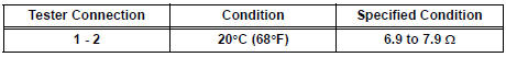
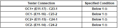
- Measure the resistance according to the value(s) in the table below.
Standard resistance
- Reconnect the OCV connector
3 CHECK HARNESS AND CONNECTOR (OCV - ECM)
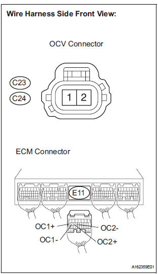
- Disconnect the C23 or C24 camshaft timing oil control valve (OCV) connector.
- Disconnect the E11 ECM connector.
- Measure the resistance according to the value(s) in the table below.
Standard resistance (Check for open)
Standard resistance (Check for short)
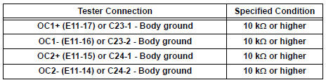
- Reconnect the OCV connector.
- Reconnect the ECM connector.
REPLACE ECM
 Diagnostic trouble code chart
HINT:
The parameters listed in the chart may not confirm exactly to
those read during the DTC check due to the type of
instrument or other factors.
If a trouble code is displayed during the DTC ...
 Camshaft Position "A" - Timing Over-Advanced
DTC P0011 Camshaft Position "A" - Timing Over-Advanced
or System Performance (Bank 1)
DTC P0012 Camshaft Position "A" - Timing Over-Retarded
(Bank 1)
DTC P0021 Camshaft Positio ...
Other materials:
SPD Signal Error
DTC 58-43 SPD Signal Error
DTC 80-43 SPD Signal Error
DESCRIPTION
DTC No.
DTC Detection Condition
Trouble Area
58-43
A difference between the GPS speed and SPD pulse is
detected.
Speed signal circuit
Radio and navigation assembly
...
Camshaft Position Sensor "B" Circuit
DESCRIPTION
The exhaust camshaft's Variable Valve Timing (VVT) sensor consists of a
magnet and MRE (Magneto
Resistance Element).
The exhaust camshaft has a sensor plate with 3 teeth on its outer circumference.
When the exhaust camshaft rotates, changes occur in the air gaps between the ...
Horn
To sound the horn, press on or
close to the mark.
WARNINGCaution while driving
Do not adjust the steering wheel while driving.
Doing so may cause the driver to mishandle the vehicle and cause an
accident,
resulting in death or serious injury.
After adjusting the steeri ...
