Toyota Sienna Service Manual: Camshaft Position Sensor
DTC P0365 Camshaft Position Sensor "B" Circuit (Bank 1)
DTC P0367 Camshaft Position Sensor "B" Circuit Low Input (Bank 1)
DTC P0368 Camshaft Position Sensor "B" Circuit High Input (Bank 1)
DTC P0390 Camshaft Position Sensor "B" Circuit (Bank 2)
DTC P0392 Camshaft Position Sensor "B" Circuit Low Input (Bank 2)
DTC P0393 Camshaft Position Sensor "B" Circuit High Input (Bank 2)
DESCRIPTION
The exhaust camshaft's Variable Valve Timing (VVT) sensor consists of a magnet and MRE (Magneto Resistance Element).
The exhaust camshaft has a sensor plate with 3 teeth on its outer circumference.
When the exhaust camshaft rotates, changes occur in the air gaps between the 3 teeth and MRE, which affects the magnet. As a result, the resistance of the MRE material fluctuates. The VVT sensor converts the exhaust camshaft rotation data to pulse signals, uses the pulse signals to determine the camshaft angle, and sends it to the ECM.
|
DTC No. |
DTC Detection Condition |
Trouble Area |
| P0365 P0390 |
|
|
| P0367 P0392 |
Output voltage of VVT sensor is 0.3 V or less for 5 seconds (1 trip detection logic) |
|
| P0368 P0393 |
Output voltage of VVT sensor is 4.7 V or more for 5 seconds (1 trip detection logic) |
|
MONITOR DESCRIPTION
If no signal is transmitted by the VVT (for exhaust camshaft) sensor despite the engine revolving, or the rotations of the exhaust camshaft and the crankshaft are not synchronized, the ECM interprets this as a malfunction of the sensor
MONITOR STRATEGY
| Related DTCs | P0365: Exhaust camshaft sensor (Bank 1) range check / rationality
(while starting
engine) P0365: Exhaust camshaft sensor (Bank 1) range check / rationality (after starting engine) P0365: Exhaust camshaft sensor (Bank 1) range check (chattering) P0367: Exhaust camshaft sensor (Bank 1) range check (low voltage) P0368: Exhaust camshaft sensor (Bank 1) range check (high voltage) P0390: Exhaust camshaft sensor (Bank 2) range check / rationality (while starting engine) P0390: Exhaust camshaft sensor (Bank 2) range check / rationality (after starting engine) P0390: Exhaust camshaft sensor (Bank 2) range check (chattering) P0392: Exhaust camshaft sensor (Bank 2) range check (low voltage) P0393: Exhaust camshaft sensor (Bank 2) range check (high voltage) |
| Required Sensors / Components (Main) | Exhaust camshaft sensor (Bank 1 and 2) |
| Required Sensors / Components (Related) | Exhaust camshaft sensor |
| Frequency of Operation | Continuous |
| Duration | 5 seconds: Exhaust camshaft sensor range check / rationality (After starting engine) 4 seconds: Others |
| MIL Operation | 2 driving cycles: Exhaust camshaft sensor range check / rationality (After starting engine) Immediate: Others |
| Sequence of Operation | None |
TYPICAL ENABLING CONDITIONS
All:
| The monitor will run whenever these DTCs are not present | None |
Exhaust Camshaft Sensor Range Check / Rationality (While starting engine):
| Starter | ON |
| Battery voltage while starter is ON at least once | Less than 11 V |
Exhaust Camshaft Sensor Range Check / Rationality (After starting engine):
| Engine RPM | 600 rpm or more |
| Starter | OFF |
| Battery voltage | 8 V or more |
| Ignition Switch | ON |
Exhaust Camshaft Sensor Range Check (Chattering, Low voltage, High voltage):
| Starter | OFF |
| Ignition Switch ON and time after ignition switch is OFF to ON | 2 seconds or more |
| Battery voltage | 8 V or more |
TYPICAL MALFUNCTION THRESHOLDS
Exhaust Camshaft Sensor Range Check / Rationality (While starting engine):
| Exhaust camshaft sensor signal | No signal |
Exhaust Camshaft Sensor Range Check / Rationality (After starting engine):
| Exhaust camshaft sensor signal | No signal |
Exhaust Camshaft Sensor Range Check (Chattering):
| Exhaust camshaft sensor signal | Less than 0.3 V, or more than 4.7 V |
Exhaust Camshaft Sensor Range Check (Low voltage):
| Exhaust camshaft sensor signal | Less than 0.3 V |
Exhaust Camshaft Sensor Range Check (High voltage):
| Exhaust camshaft sensor signal | More than 4.7 V |
WIRING DIAGRAM
Refer to DTC P0335
INSPECTION PROCEDURE
HINT: Read freeze frame data using the intelligent tester. The ECM records vehicle and driving condition information as freeze frame data the moment a DTC is stored. When troubleshooting, freeze frame data can be helpful in determining whether the vehicle was running or stopped, whether the engine was warmed up or not, whether the air-fuel ratio was lean or rich, as well as other data recorded at the time of a malfunction.
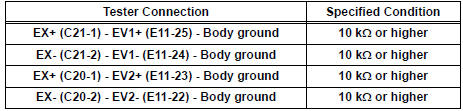
1 CHECK VVT SENSOR FOR EXHAUST CAMSHAFT (SENSOR POWER SOURCE)
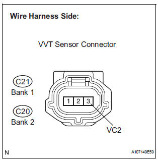
- Disconnect the C21 or C20 VVT sensor connector.
- Measure the voltage according to the value(s) in the table below.
Standard voltage
OK
2 CHECK HARNESS AND CONNECTOR (VVT SENSOR - ECM)
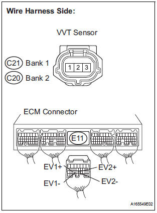
- Disconnect the C21 or C20 VVT sensor for exhaust camshaft connector.
- Disconnect the E11 ECM connector.
- Measure the resistance between the wire harness side connectors.
Standard resistance: Check for open
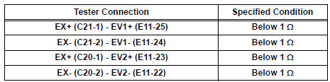
Check for short
OK
3 CHECK VVT SENSOR FOR EXHAUST CAMSHAFT (SENSOR INSTALLATION)
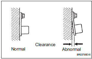
- Check the VVT sensor installation.
OK: Sensor is installed correctly.
NG
OK REPAIR OR REPLACE VVT SENSOR
4 CHECK EXHAUST CAMSHAFT
- Check the teeth of the camshaft
NG REPLACE EXHAUST CAMSHAFT
OK
5 REPLACE VVT SENSOR (FOR EXHAUST CAMSHAFT)
- Replace the VVT sensor
NEXT
6 CHECK WHETHER DTC OUTPUT RECURS
- Connect the intelligent tester to the DLC3.
- Turn the ignition switch to the ON position.
- Turn the intelligent tester on.
- Clear the DTCs.
- Select the following menu items: DIAGNOSIS / ENHANCED OBD II / DTC / INFO / PENDING CODES.
- Read the DTCs
Result

HINT: If the engine does not start, replace the ECM.
B REPLACE ECM
A
END
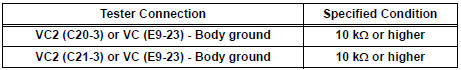
7 CHECK HARNESS AND CONNECTOR (VVT SENSOR - ECM)
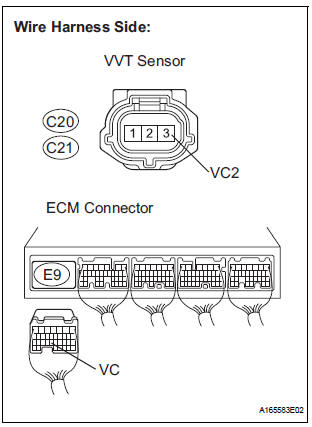
- Disconnect the C18 or C19 VVT sensor connector.
- Disconnect the E9 ECM connector.
- Measure the resistance according to the value(s) in the table below.
Standard resistance : Check for open
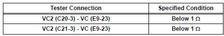
Check for short
- Reconnect the VVT sensor connector.
- Reconnect the ECM connector
NG REPAIR OR REPLACE HARNESS OR CONNECTOR (VVT SENSOR - ECM)
OK
REPLACE ECM
 Ignition Coil Primary / Secondary Circuit
DTC P0351 Ignition Coil "A" Primary / Secondary Circuit
DTC P0352 Ignition Coil "B" Primary / Secondary Circuit
DTC P0353 Ignition Coil "C" Primary / Secondary Circuit
...
 Catalyst System Efficiency Below Threshold
DTC P0420 Catalyst System Efficiency Below Threshold
(Bank 1)
DTC P0430 Catalyst System Efficiency Below Threshold
(Bank 2)
MONITOR DESCRIPTION
The ECM uses the sensors mounted in front of and be ...
Other materials:
Open or Short Circuit in ABS Motor Relay Circuit
DESCRIPTION
The ABS motor relay supplies power to the ABS pump motor. While the ABS &
TRAC & VSC are
activated, the ECU switches the ABS motor relay ON and operates the ABS pump
motor.
WIRING DIAGRAM
INSPECTION PROCEDURE
1 PERFORM ACTIVE TEST USING INTELLIGENT TESTER (AB ...
Short to GND in Front Passenger Side Squib
2nd Step Circuit
DTC B1187/55 Short to GND in Front Passenger Side Squib
2nd Step Circuit
DESCRIPTION
The front passenger side squib 2nd step circuit consists of the center airbag
sensor assembly and the
front passenger airbag assembly.
The circuit instructs the SRS to deploy when deployment conditions are ...
Installation
1. INSTALL TRANSMISSION CONTROL CABLE ASSEMBLY
(a) Pull in the control cable to the body.
(b) Install the cable end, as shown in the illustration.
(c) When installing the transmission control cable
assembly on the shift lever plate, place the
projection of the shift cable downward to ...
