Toyota Sienna Service Manual: Check for open circuit
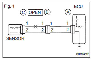
(a) For an open circuit in the wire harness in Fig. 1, the resistance or voltage, as described below.
(b) Check the resistance.
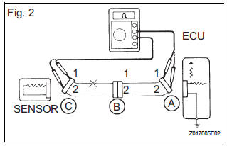
Check the resistance
Standard resistance (Fig. 2)
HINT:
Measure the resistance while lightly shaking the wire harness vertically and horizontally. If the results match the examples above, an open circuit exists between terminal 1 of connector A and terminal 1 of connector C.
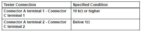
(2) Disconnect connector B and measure the resistance between the terminals of the connectors.
Standard resistance (Fig. 3)
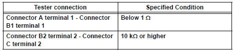
If the results match the examples above, an open circuit exists between terminal 1 of connector B2 and terminal 1 of connector C.
(c) Check the voltage.
Check the voltage
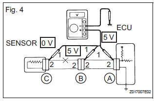
(1) In a circuit in which voltage is applied to the ECU connector terminal, an open circuit can be checked by conducting a voltage check.
With each connector still connected, measure the voltage between the body ground and these terminals (in this order): 1) terminal 1 of connector A, 2) terminal 1 of connector B, and 3) terminal 1 of connector C.
Standard voltage (Fig. 4)
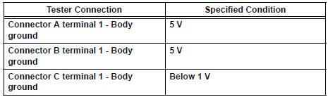
If the results match the examples above, an open circuit exists in the wire harness between terminal 1 of connector B and terminal 1 of connector C.
 Basic inspection
(a) WHEN MEASURING RESISTANCE OF
ELECTRONIC PARTS
(1) Unless otherwise stated, all resistance
measurements should be made at an ambient
temperature of 20°C (68°F). Resistance
measurements may b ...
 Check for short circuit
(a) If the wire harness is ground shorted (Fig. 5), locate the section by
conducting a resistance check with the body ground (below).
(b) Check the resistance with the body ground.
...
Other materials:
Power slide door warning buzzer
INSPECTION
1. INSPECT POWER SLIDE DOOR WARNING BUZZER LH
Check the resistance of the buzzer.
Resistance
If the result is not as specified, replace the buzzer.
NOTICE:
The circuit that causes the buzzer to sound is
built into the slide door ECU, not around the
buzzer.
Direct ...
Summary of the Blind Spot Monitor
The Blind Spot Monitor is a system that has 2 functions:
The Blind Spot Monitor function
Assists the driver in making the decision when changing lanes
The Rear Cross Traffic Alert function
Assists the driver when backing up
These functions use same sensors.
BSM main switch
Pre ...
Installation
1. INSTALL KNOCK CONTROL SENSOR
Install the 2 knock control sensors with the 2 bolts
as shown in the illustration.
Torque: 20 N*m (204 kgf*cm, 15 ft.*lbf)
Connect the 2 knock control sensor connectors.
2. INSTALL INTAKE MANIFOLD
3. INSTALL FUEL MAIN TUBE SUB-ASSEMBLY
4 ...
