Toyota Sienna 2010-2026 Owners Manual: Clock setting
- Display the ÔÇťGeneral SettingsÔÇŁ screen. Operations up to this point can also be performed by select the clock display at the top of most screens.
- Select the items to be set.
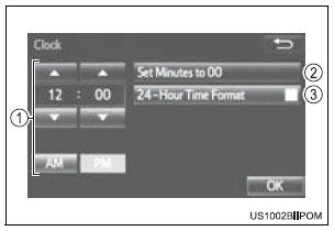
- Manual clock setting
- Set minutes to 00
- The 24-hour time format can be to on/off.
- Select ÔÇťOKÔÇŁ.
 Screen for general settings
Press the ÔÇťSETUPÔÇŁ button.
Select ÔÇťGeneralÔÇŁ on the ÔÇťSetupÔÇŁ
screen.
Select to adjust the clock.
ÔÇťEnglishÔÇŁ, ÔÇťFrançaisÔÇŁ or
ÔÇťEspañolÔÇŁ can be ...
 Delete personal data
Select ÔÇťDelete Personal DataÔÇŁ on the ÔÇťGeneral SettingsÔÇŁ screen.
Select ÔÇťDeleteÔÇŁ.
Check carefully beforehand, as data cannot be retrieved once deleted.
A confirmation screen will b ...
Other materials:
Insufficient Coolant Temperature for Closed Loop Fuel Control
DESCRIPTION
Refer to DTC P0115 (See page ES-133).
MONITOR DESCRIPTION
The resistance of the ECT sensor varies in proportion to the actual ECT. The
ECM supplies a constant
voltage to the sensor and monitors the signal output voltage of the sensor. The
signal voltage output
varies acc ...
Fuel pump shut off
system
To minimize the risk of fuel leakage when the engine stalls or
when an airbag inflates upon collision, the fuel pump shut off
system stops the supply of fuel to the engine.
Follow the procedure below to restart the engine after the system is
activated.
Vehicles without a smart key system
...
Removal
1. RECOVER REFRIGERANT FROM REFRIGERATION
SYSTEM (See page AC-172)
2. REMOVE NO. 2 AIR CLEANER INLET (See page EM-
28)
3. REMOVE FRONT BUMPER ASSEMBLY (See page
ET-3)
4. DISCONNECT DISCHARGE HOSE SUB-ASSEMBLY
(a) Remove the bolt and disconnect the discharge hose
sub-assembly from the coo ...
