
Toyota Sienna Service Manual: Components
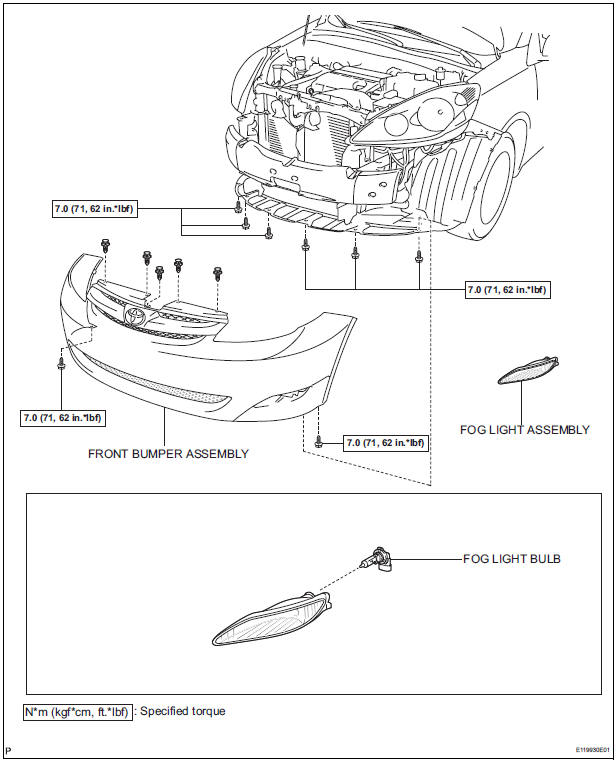
REMOVAL
1. DISCONNECT CABLE FROM NEGATIVE BATTERY TERMINAL
2. REMOVE FRONT BUMPER ASSEMBLY
3. REMOVE FOG LIGHT ASSEMBLY
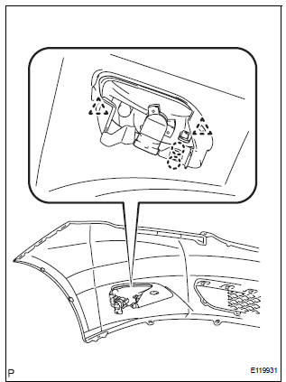
- Disengage the 2 claws
- Disengage the 2 pins and remove the fog light assembly.
DISASSEMBLY
1. REMOVE FOG LIGHT BULB
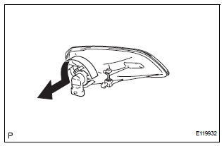
- Turn in the direction indicated by the arrow and remove the fog light bulb.

 Adjustment
1. VEHICLE PREPARATION FOR FOG LIGHT AIMING
Prepare the vehicle:
Ensure there is no damage or deformation to the
body around the fog lights.
Fill the fuel tank.
...
Other materials:
On-vehicle inspection
1. CONNECT INTELLIGENT TESTER
(a) Connect the intelligent tester to the DLC3.
(b) Start the engine and run at idle.
(c) Select the ACTIVE TEST mode on the intelligent
tester.
HINT:
Please refer to the intelligent tester operator's
manual for further details.
2. INSPECT ACTUATOR MOTOR ...
Vehicle exterior
Items
Check points
Doors
Do the doors operate smoothly?
Engine hood
Does the engine hood lock system work
properly?
Fluid leaks
There should not be any signs of fluid
leakage after the vehicle ha ...
Installation
1. INSTALL REAR NO. 2 SEAT ASSEMBLY
Lock the seat leg rear to the floor striker.
Lock the seat leg front to the floor striker.
Install the rear No. 2 seat assembly with the 6 bolts.
Torque: 19 N*m (194 kgf*cm, 14 ft.*lbf)
NOTICE:
Tighten the bolts in the order sho ...
