Toyota Sienna Service Manual: Compressor Lock Sensor Circuit
DTC B1422/22 Compressor Lock Sensor Circuit
SYSTEM DESCRIPTION
The ECM sends an engine speed signal to the A/C amplifier via CAN communication and BEAN communication.
The A/C amplifier reads the difference between compressor speed and engine
speed. When the
difference becomes too large, the A/C amplifier determines that the compressor
locks, and turns the
magnetic clutch off.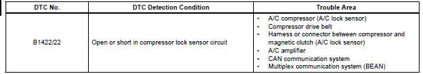
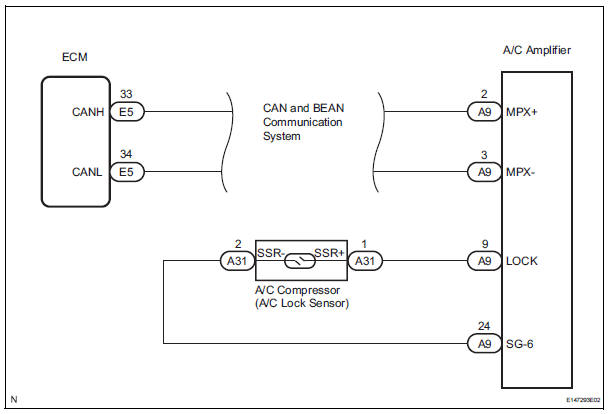
WIRING DIAGRAM
INSPECTION PROCEDURE
1 CHECK CAN COMMUNICATION SYSTEM
(a) Use the intelligent tester to check if the CAN communication system is functioning normally.
Result 


2 CHECK MULTIPLEX COMMUNICATION SYSTEM
(a) Use the intelligent tester to check if the multiplex communication system (BEAN) is functioning normally.
Result 

3 INSPECT A/C AMPLIFIER
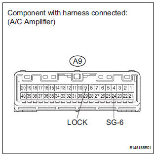
(a) Remove the A/C amplifier with the connectors still connected.
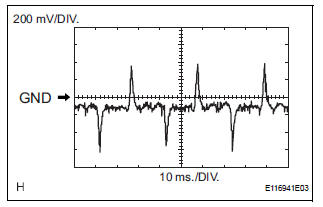
(b) Measure the waveform of the connector.
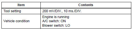
Standard 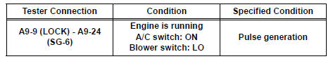
Result 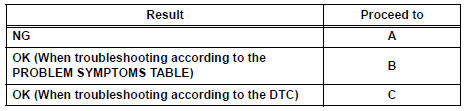

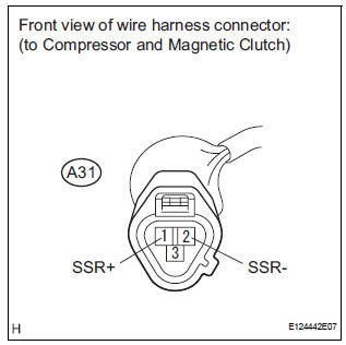
4 INSPECT COMPRESSOR AND MAGNETIC CLUTCH (A/C LOCK SENSOR)
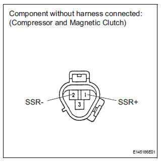
(a) Disconnect the connector from the A/C compressor.
(b) Measure the resistance according to the value(s) in the table below.
Standard resistance 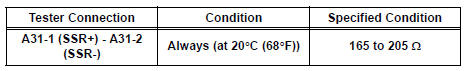

5 CHECK HARNESS AND CONNECTOR (A/C AMPLIFIER - A/C LOCK SENSOR)
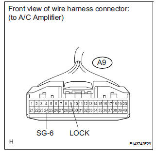
(a) Disconnect the connector from the A/C amplifier.
(b) Measure the resistance according to the value(s) in the table below.
Standard resistance 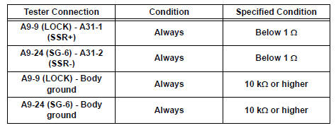

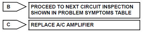
REPLACE A/C AMPLIFIER
 Solar Sensor Circuit (Passenger Side)
DTC B1421/21 Solar Sensor Circuit (Passenger Side)
DESCRIPTION
The solar sensor, which is installed on the upper side of the instrument
panel, detects sunlight and
controls the air conditioni ...
 Pressure Sensor Circuit
DTC B1423/23 Pressure Sensor Circuit
DESCRIPTION
This DTC is output when refrigerant pressure on the high pressure side is
extremely low (0.19 MPa (2.0
kgf/cm2, 28 psi) or less) or extremely high ...
Other materials:
System description
1. GENERAL
The dynamic laser cruise control system has two
cruise control modes: the constant speed control
mode and vehicle-to-vehicle distance control mode.
The vehicle-to-vehicle distance control mode is
always selected when starting the dynamic laser
cruise control ...
Disassembly
1. REMOVE FRONT SEAT SIDE TABLE LEG COVER (w/
Table)
Using a screwdriver, disengage the claws and
remove the seat side table leg cover.
HINT:
Tape the screwdriver tip before use.
2. REMOVE FRONT SEAT SIDE TABLE (w/ Table)
Remove the 4 nuts and seat side table.
Rem ...
Removal
1. DISCHARGE FUEL SYSTEM PRESSURE
2. REMOVE V-BANK COVER SUB-ASSEMBLY
3. DRAIN ENGINE COOLANT
4. REMOVE WINDSHIELD WIPER MOTOR ASSEMBLY
5. REMOVE FRONT OUTER COWL TOP PANEL SUBASSEMBLY
6. REMOVE AIR CLEANER CAP SUB-ASSEMBLY
7. REMOVE AIR CLEANER CASE SUB-ASSEMBLY
8. REMOVE INTAKE AIR SURGE TA ...
