Toyota Sienna Service Manual: Condenser
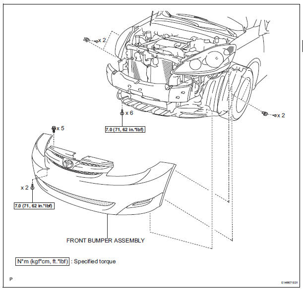
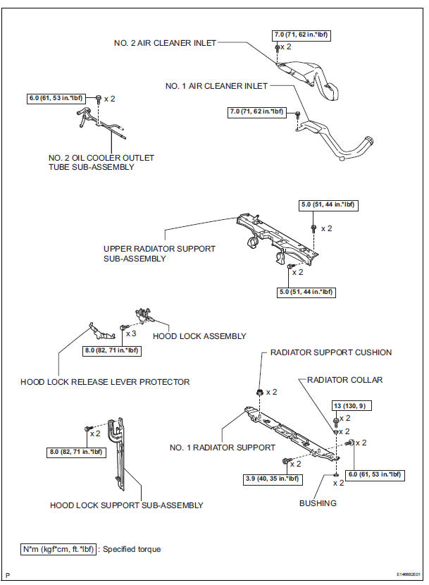
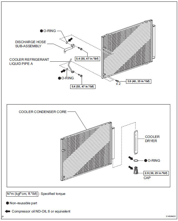
COMPONENTS
 Installation
1. INSTALL COMPRESSOR AND MAGNETIC CLUTCH
(a) Using a "TORX" socket wrench (E8), install the
compressor and magnetic clutch with the 2 stud
bolts.
Torque: 10 N*m (102 kgf*cm, 7.4 ft. ...
 On-vehicle inspection
1. INSPECT COOLER CONDENSER CORE
(a) If the fin of the cooler condenser core is dirty, clean
it with water and dry it with compressed air.
NOTICE:
Do not damage the fin of the cooler condenser
co ...
Other materials:
Open in Occupant Classification ECU Battery
Positive Line
DTC B1794 Open in Occupant Classification ECU Battery
Positive Line
DESCRIPTION
This circuit consists of the occupant classification ECU and the power source
circuit (battery, fuse, wire
harness).
DTC B1794 is recorded when a malfunction is detected in the occupant
classification ECU or t ...
Terminals of ECU
1. CHECK POWER BACK DOOR ECU
Disconnect the P13 and P14 ECU connectors, and
check the voltage and resistance of each terminal of
the wire harness side connectors
If the result is not as specified, there may be a
malfunction on the wire harness side.
Reconnect the ECU co ...
Transmitter ID1 Error
DESCRIPTION
The tire pressure warning valve and transmitters that are installed in the
tire and wheel assemblies
measure the air pressure of the tires. The measured values are transmitted to
the tire pressure warning
antenna and receiver on the body as radio waves and then sent to the tir ...
