Toyota Sienna Service Manual: Cooling fan ecu
ON-VEHICLE INSPECTION
1. INSPECT COOLING FAN ECU
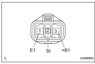
(a) Inspect the input voltage.
(1) Disconnect the cooling fan ECU connector.
(2) Turn the ignition switch to the ON position.
Check the voltage of the +B terminal of the disconnected wire harness side connector.
Standard voltage: 9 to 14 V
If the result is not as specified, inspect the power source system (fusible link, fuse, wire harness and relay).
(b) Inspect the cooling fan motor (See page CO-19).
(c) Measure the resistance between terminals RFC (ECM) and SI (cooling fan ECU) of the wire harness side connectors.V
HINT:
- If the fan does not operate, there may be a short circuit.
- If the fan remains operating, there may be an open circuit.
(d) Inspect the ECM power source circuit and ground circuit.
 Cooling fan motor
On-vehicle inspection
1. No. 1 Cooling fan motor
(A) check that the motor turns smoothly when the
battery is connected to the fan motor connector.
(B) measure the current while the motor is ...
 Cooling fan relay
On-vehicle inspection
1. Cooling fan relay
(a) Remove the relay from engine room relay block No.
1.
(b) Measure the resistance of the relay.
Standard resistance
If the result is not as ...
Other materials:
Terminals of ECU
1. CHECK TRANSPONDER KEY AMPLIFIER
Disconnect the I14 amplifier connector and measure
the resistance between the terminal of the wire
harness side connector and body ground.
If the result is not as specified, there may be a
malfunction on the wire harness side.
Reconnec ...
Initialization
1. RESET
When the back door lock is replaced:
The power back door ECU cannot receive a switch
signal from the lock. This may cause the power
back door system to enter fail-safe mode and DTC
B2215 to set, and also make the system disabled.
When the lock is replaced, be sure to perform t ...
Throttle Actuator Control System
DESCRIPTION
The throttle actuator is operated by the ECM, and opens and closes the
throttle valve using the gears.
The opening angle of the throttle valve is detected by the Throttle Position
(TP) sensor, which is mounted
on the throttle body. The TP sensor provides feedback to the ECM ...
