Toyota Sienna Service Manual: Cruise Control Switch Circuit
DESCRIPTION
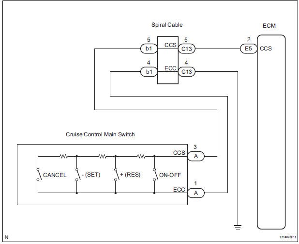
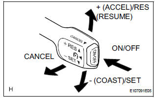
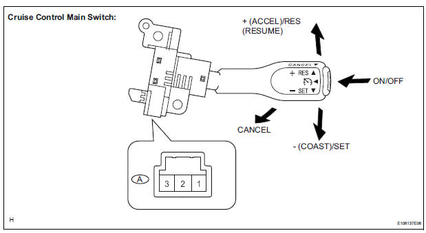
The cruise control main switch operates 7 functions: SET, - (COAST), TAP-DOWN, RES (RESUME), + (ACCEL), TAP-UP, and CANCEL. The SET, TAP-DOWN, and - (COAST) functions, and the RES (RESUME), TAP-UP, and + (ACCEL) functions are operated with the same switch. The cruise control main switch is an automatic return type switch which turns on only while operating it in the direction of each arrow and turns off after releasing it. The internal contact point of the cruise control main switch is turned on with the switch operation. Then the ECM reads the voltage value that has been changed by the switch operation to control SET, - (COAST), RES (RESUME), + (ACCEL), and CANCEL.
WIRING DIAGRAM
INSPECTION PROCEDURE
1 READ VALUE OF INTELLIGENT TESTER
- Connect the intelligent tester to the DLC3.
- Turn the ignition switch to the ON position and turn the intelligent tester main switch on.
- Check the DATA LIST for proper functioning of the cruise control main switch.
ECM (Cruise control):
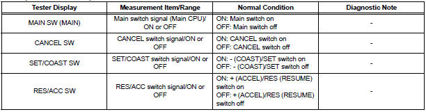
OK: When the cruise control main switch is operated, the display changes as shown above.
Result
2 INSPECT CRUISE CONTROL MAIN SWITCH
- Remove the cruise control main switch.
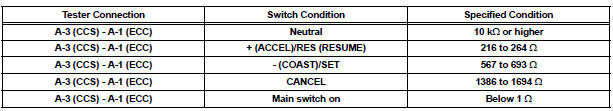
- Measure the resistance according to the value(s) in the table below.
Standard resistance
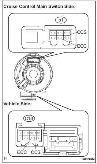
3 CHECK HARNESS AND CONNECTOR (CRUISE CONTROL MAIN SWITCH - SPIRAL CABLE)
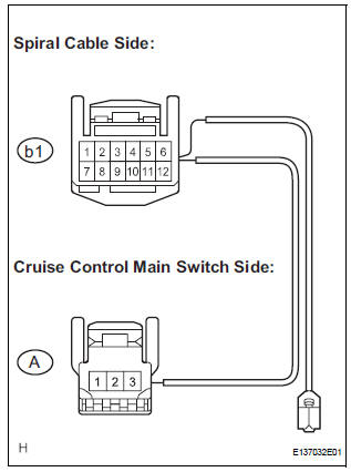
- Disconnect the b1 connector from the spiral cable.
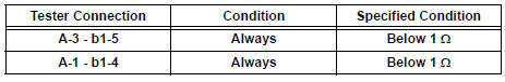
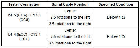
- Measure the resistance according to the value(s) in the table below.
Standard resistance
4 CHECK SPIRAL CABLE
NOTICE: The spiral cable is an important part of the SRS airbag system. Incorrect removal or installation of the spiral cable may prevent the airbag from deploying. Be sure to read the page shown in the brackets.
HINT:
- Removal (34)
- Installation (34)
- Remove the spiral cable.
- Measure the resistance according to the value(s) in the table below.
Standard resistance
HINT: The spiral cable makes a maximum of approximately 5 rotations.
CHECK HARNESS AND CONNECTOR (SPIRAL CABLE - ECM AND BODY GROUND)
- Disconnect the E5 connector from the ECM.
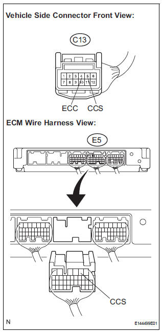
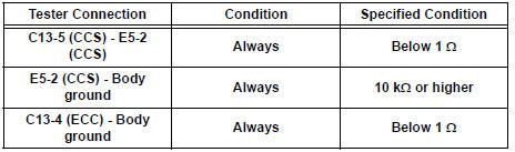
- Measure the resistance according to the value(s) in the table below.
Standard resistance
REPLACE ECM
 Input Signal Circuit Malfunction
DTC P0607 Input Signal Circuit Malfunction
DESCRIPTION
This DTC indicates internal abnormalities of the ECM.
DTC No.
Detection Item
Trouble Area
P0607
The E ...
 Cruise Main Indicator Light Circuit
DESCRIPTION
The ECM detects a cruise control switch signal and sends it to the
combination meter through CAN
and BEAN. Then the CRUISE main indicator light comes on.
The CRUISE ...
Other materials:
Diagnosis system
1. CHECK DLC3
The vehicle's ECU uses ISO 15765-4 for
communication protocol. The terminal arrangement
of the DLC3 complies with SAE J1962 and matches
the ISO 15765-4 format.
NOTICE:
*: Before measuring the resistance, leave the
vehicle as is for at least 1 minute and do not
...
Fuel pump resistor
Components
REMOVAL
1. REMOVE FUEL PUMP RESISTOR
(a) Disconnect the connector.
(b) Remove the nut and fuel pump resistor.
INSPECTION
1. INSPECT FUEL PUMP RESISTOR
(a) Inspect fuel pump resistor.
(1) Using an ohmmeter, measure the resistance
between the terminals.
Standard resi ...
Power mirror control system (w/o Memory)
PARTS LOCATION
Problem symptoms table
POWER MIRROR CONTROL SYSTEM
Symptom
Suspected area
Mirror does not operate
Outer mirror switch assembly
Outer rear view mirror assembly
Wire harness
Mirror operates abnormally
O ...
