Toyota Sienna Service Manual: Cruise Main Indicator Light Circuit
DESCRIPTION
- The ECM detects a cruise control switch signal and sends it to the combination meter through CAN and BEAN. Then the CRUISE main indicator light comes on.
- The CRUISE main indicator light circuit uses CAN and BEAN for communication. If there is a malfunction in this circuit, check for DTCs in the CAN communication system and multiplex communication system before troubleshooting this circuit.
INSPECTION PROCEDURE
1 PERFORM ACTIVE TEST BY INTELLIGENT TESTER
- Connect the intelligent tester to the DLC3.
- Turn the ignition switch to the ON position and turn the intelligent tester main switch on.
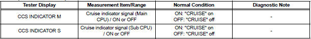
- Check the CRUISE main indicator light by performing the ACTIVE TEST.
METER:

OK: The indicator light blinks/goes off.
2 READ VALUE OF INTELLIGENT TE
- Connect the intelligent tester to the DLC3.
- Turn the ignition switch to the ON position and turn the intelligent tester main switch on.
- Check the DATA LIST for proper functioning of the CRUISE main indicator light.
ECM (Cruise control):
OK: When the cruise control main switch is operated, the display changes as shown above.
PROCEED TO NEXT CIRCUIT INSPECTION SHOWN IN PROBLEM SYMPTOMS TABLE
 Cruise Control Switch Circuit
DESCRIPTION
The cruise control main switch operates 7 functions: SET, - (COAST),
TAP-DOWN, RES (RESUME), +
(ACCEL), TAP-UP, and CANCEL. The SET, TAP-DOWN, and - (COAST) functions, and the
RES
( ...
 TC and CG Terminal Circuit
DESCRIPTION
Connecting terminals TC and CG of the DLC3 causes the system to enter the
self-diagnostic mode. If a
malfunction is present, DTCs will be output.
HINT:
When a particular warning li ...
Other materials:
Oxygen Sensor Heater Control Circuit
HINT:
Sensor 2 refers to the sensor mounted behind the Three-Way Catalytic
Converter (TWC) and located
furthest from the engine assembly.
DESCRIPTION
Refer to DTC P0136 (See page ES-160).
HINT:
When any of these DTCs are set, the ECM enters fail-safe mode. The ECM turns
off the Heated ...
Open in Front Pretensioner Squib RH Circuit
DTC B0131/64 Open in Front Pretensioner Squib RH Circuit
DESCRIPTION
The front pretensioner squib RH circuit consists of the center airbag sensor
assembly and the front seat
outer belt assembly RH.
This circuit instructs the SRS to deploy when deployment conditions are met.
DTC B0131/64 i ...
Front door lock
INSPECTION
1. INSPECT FRONT DOOR W/ MOTOR LOCK ASSEMBLY LH
Apply battery voltage to the door lock and check
operation of the motor.
OK
HINT:
If the result is not as specified, replace the door lock
assembly.
Measure the resistance according to the value(s) in
the table ...
