
Toyota Sienna Service Manual: Data list / active test
1. DATA LIST
HINT: Using the intelligent tester to read the Data List allows the values or states of switches, sensors, actuators and other items to be read without removing any parts. This non-intrusive inspection can be very useful because intermittent conditions or signals may be discovered before parts or wiring is disturbed. Reading the Data List information early in troubleshooting is one way to save diagnostic time.
(a) Connect the intelligent tester to the DLC3.
(b) Turn the ignition switch to the ON position.
(c) From the display on the tester, read the "DATA LIST".
AIR CONDITIONER / DATA LIST
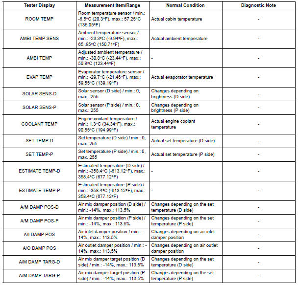
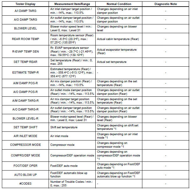
HINT: *1: It differs depending on the user setting.
2. ACTIVE TEST
HINT: Using the intelligent tester to perform Active Tests allows relays, VSVs, actuators and other items to be operated without removing any parts. This non-intrusive functional inspection can be very useful because intermittent operation may be discovered before parts or wiring is disturbed. Performing Active Tests early in troubleshooting is one way to save diagnostic time. Data List information can be displayed while performing Active Tests.
(a) Connect the intelligent tester to the DLC3.
(b) Turn the ignition switch to the ON position.
(c) From the display on the tester, read the "ACTIVE TEST".
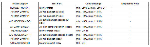
 Check mode procedure
1. LIST OF OPERATION METHODS
By operating each of the A/C control switches as shown
in the diagram below, it is possible to enter the diagnosis
check mode.
...
 Diagnostic trouble code chart
If a trouble code is displayed during the DTCs check (sensor
check), check the circuit listed for the code in the table below
(Proceed to the page given for that circuit).
AIR CONDITIONING SYSTEM
...
Other materials:
Disassembly
1. REMOVE PROPELLER SHAFT ASSEMBLY
(a) Put matchmarks on both the flanges.
(b) Remove the 4 nuts, bolts and washers.
2. REMOVE INTERMEDIATE SHAFT
(a) Put matchmarks on the propeller shaft subassembly
and universal joint flange.
NOTICE:
Do not use a punch for the marks.
(b) Using a ...
Short to GND in Rear Curtain Shield Squib LH
Circuit
DTC B1637/85 Short to GND in Rear Curtain Shield Squib LH
Circuit
DESCRIPTION
The rear curtain shield squib LH circuit consists of the center airbag sensor
assembly and the curtain
shield airbag assembly LH.
The circuit instructs the SRS to deploy when deployment conditions are met.
DTC ...
Removal
1. REMOVE CHARCOAL CANISTER PROTECTOR
(a) Remove the 6 bolts and charcoal canister protector.
2. REMOVE CHARCOAL CANISTER ASSEMBLY
(a) Disconnect the fuel tank vent hose from the
charcoal canister.
(1) Push the connector deep inside.
(2) Pinch portion A.
(3) Pull out the connector.
...
