
Toyota Sienna Service Manual: Data list / active test
HINT: By accessing the DATA LIST displayed on the intelligent tester, you can perform such functions as reading the values of switches and sensors without removing any parts. Reading the DATA LIST as the first step in troubleshooting is one method to shorten labor time.
1. DATA LIST FOR CENTER AIRBAG SENSOR ASSEMBLY
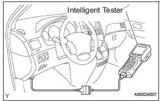
- Connect the intelligent tester to the DLC3.
- Turn the ignition switch to the ON position.
- Turn the tester on.
- Enter the following menus: DIAGNOSIS / OBD/ MOBD / SRS AIRBAG / DATA LIST.
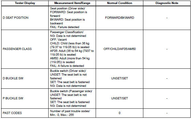
- Check the values by referring to the table below.
DATA LIST:
 Check mode procedure
1. CHECK MODE (SIGNAL CHECK): DTC CHECK
Connect the intelligent tester to the DLC3.
) Turn the ignition switch to the ON position.
) Select the "SIGNAL CHECK", and proceed
...
 Diagnostic trouble code chart
1. DTCS FOR AIRBAG SYSTEM
If a malfunction code is displayed during the DTC check,
check the circuit listed for the code in the table below
(Proceed to the page listed for that circuit).
HINT:
...
Other materials:
Terminals of ECU
1. CENTER AIRBAG SENSOR ASSEMBLY (w/ Side
Airbag)
2. CENTER AIRBAG SENSOR ASSEMBLY (w/o Side
Airbag)
...
Slide door lock release motor
Inspection
1. INSPECT SLIDE DOOR LOCK RELEASE MOTOR ASSEMBLY LH
Apply battery voltage and inspect operation of the
motor.
OK
If the result is not as specified, replace the motor
assembly.
2. INSPECT SLIDE DOOR LOCK RELEASE MOTOR ASSEMBLY RH
Apply battery voltage and insp ...
Vehicle Speed Signal Circuit between Stereo Component Amplifier and
Combination Meter
DESCRIPTION
This circuit is necessary for the ASL (Auto Sound Leveliser) built into the
stereo component amplifier.
Speed signals are received from the combination meter and used for the ASL.
The ASL function automatically adjusts the sound data in order to enable hearing
the clear audio ...
