Toyota Sienna Service Manual: Data list / active test
1. DATA LIST
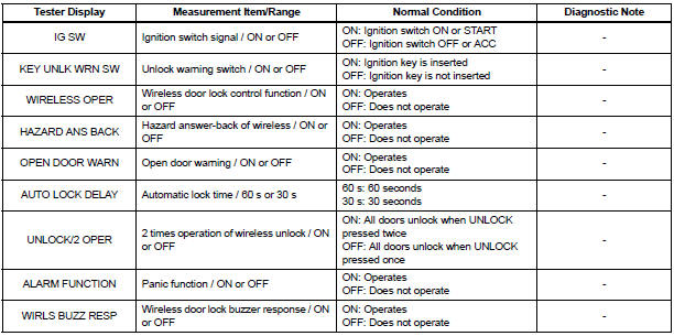
- The wireless door lock control data list can be
displayed while the intelligent tester is connected to
the DLC3 with the ignition switch in the ON position.
Follow the prompts on the tester screen to access the DATA LIST.
BODY:
2. ACTIVE TEST
HINT: Performing the ACTIVE TEST using the intelligent tester allows components such as the relay, VSV and actuator to operate without removing parts. Performing the ACTIVE TEST as the first step in troubleshooting is one way to shorten labor time.
It is possible to display the DATA LIST during the ACTIVE TEST.
- Connect the intelligent tester to the DLC3.
- Turn the ignition switch to the ON position.
- According to the display on the tester, preform the ACTIVE TEST.
HINT: The ignition switch must be turned to the ON position to proceed with the ACTIVE TEST using the intelligent tester.
BODY:

 DTC check / clear
1. DTC CHECK/CLEAR (USING INTELLIGENT TESTER:)
DTC check
Connect the intelligent tester to the DLC3.
Turn the ignition switch to the ON position.
Read the DTCs on t ...
 Diagnostic trouble code chart
HINT:
If a trouble code is displayed during the DTC check,
inspect the circuit listed for that code. For details of the
code, refer to the "See page" in the DTC chart.
...
Other materials:
Installation
1. INSTALL SLIDE DOOR ROLLER ASSEMBLY UPPER
Apply MP grease to the rotating area of the roller.
Install the roller with the 2 bolts.
Torque: 13 N*m (130 kgf*cm, 10 ft.*lbf)
2. INSTALL SLIDE DOOR HINGE ASSEMBLY CENTER LH
Apply MP grease to the rotating areas of the hinge.
Ins ...
System check
HINT:
Performing a SYSTEM CHECK enables the system,
which consists of the multiple actuators, to be operated
without removing any parts. In addition, it can show
whether or not any DTCs are set, and can detect
potential malfunctions in the system. The SYSTEM
CHECK can be performed with an inte ...
Rear Occupant Classification Sensor LH Collision
Detection
DTC B1787 Rear Occupant Classification Sensor LH Collision
Detection
DESCRIPTION
DTC B1787 is output when the occupant classification ECU receives a collision
detection signal sent by
the rear occupant classification sensor LH if an accident occurs.
DTC B1787 is also output when the front s ...
