
Toyota Sienna Service Manual: Daytime running light resister
On-vehicle inspection
1. DRL RESISTOR
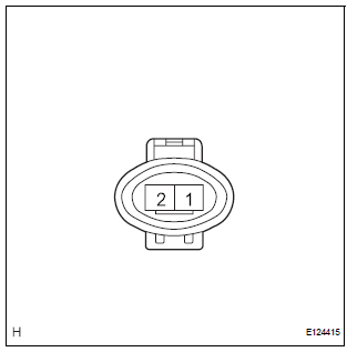
- Check that there is resistance between the terminals as shown in the chart.
Resistance

 Repair
1. INSTALL HEADLIGHT PROTECTOR RETAINER UPPER
HINT:
If the installation area of the headlight assembly is
damaged, use the supply bracket for low-cost repair.
Ensure that the headli ...

Other materials:
Compressor Solenoid Circuit
DESCRIPTION
In this circuit, the compressor receives a refrigerant compression demand
signal from the A/C amplifier.
Based on this signal, the compressor changes the amount of compressor output.
WIRING DIAGRAM
INSPECTION PROCEDURE
1 INSPECT A/C COMPRESSOR
(a) Disconnect the A/C com ...
Problem symptoms table
HINT:
Use the table below to help determine the cause of the
problem symptom. The likely causes of the problem are
indicated in descending order. Check each suspected area
in order. Repair or replace faulty parts or perform
adjustments as necessary.
Inspect the fuse and rel ...
On-vehicle inspection
1. INSPECT CAMSHAFT TIMING CONTROL VALVE ASSEMBLY
Connect the intelligent tester to the DLC3.
Turn the ignition switch to the ON position.
Start the engine and warm it up.
Select the intelligent tester from the ACTIVE TEST
menu.
Check the engine speed ...
