Toyota Sienna Service Manual: Diagnosis Circuit
DESCRIPTION
DTC output mode is set by connecting terminals TC and CG of the DLC3.
DTCs are displayed by blinking the SRS warning light.
HINT:
- When each warning light stays blinking, a ground short in the wiring of terminal TC of the DLC3 or an internal ground short in each ECU is suspected.
- A DTC output mode signal is transmitted through BEAN and CAN to each ECU including the center airbag sensor assembly. Thus when all systems do not enter DTC output mode, there may be an ECM malfunction
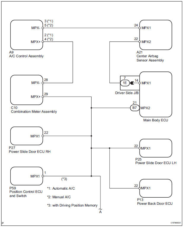
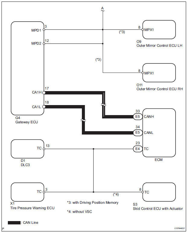
WIRING DIAGRAM
INSPECTION PROCEDURE
1 CHECK MULTIPLEX COMMUNICATION SYSTEM
- Check if the multiplex communication system DTC is output.
HINT: The center airbag sensor assembly of this system is connected to the multiplex communication system.
Therefore, before starting troubleshooting, make sure to check that there is no trouble in the multiplex communication system.
OK: The Multiplex communication system DTC is not output.
 REPAIR CIRCUITS INDICATED BY
OUTPUT
DTCS
REPAIR CIRCUITS INDICATED BY
OUTPUT
DTCS

2 CHECK CAN COMMUNICATION SYSTEM
- Use the intelligent tester to check if the CAN communication system is functioning normally.
HINT: The ECM is connected to the CAN communication system. Therefore, before starting troubleshooting, make sure to check that there is no trouble in the CAN communication system.
OK: The CAN communication system is functioning normally.
 REPAIR CAN COMMUNICATION
CIRCUIT
REPAIR CAN COMMUNICATION
CIRCUIT

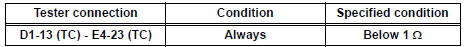
3 CHECK WIRE HARNESS (TC OF DLC3 - TC OF ECM)
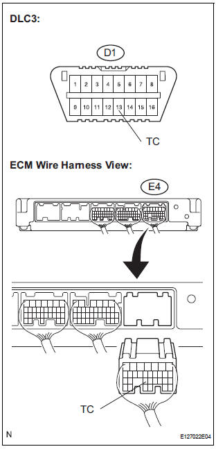
- Turn the ignition switch to the LOCK position.
- Disconnect the connector from the ECM.
- Measure the resistance according to the value(s) in the table below.
Standard resistance
 REPAIR OR REPLACE WIRE
HARNESS (TC
OF DLC3 - TC OF ECM)
REPAIR OR REPLACE WIRE
HARNESS (TC
OF DLC3 - TC OF ECM)

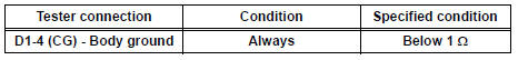
4 CHECK WIRE HARNESS (CG OF DLC3 - BODY GROUND)
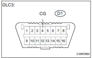
- Measure the resistance according to the value(s) in the table below.
Standard resistance
 REPAIR OR REPLACE WIRE
HARNESS (CG
OF DLC3 - BODY GROUND)
REPAIR OR REPLACE WIRE
HARNESS (CG
OF DLC3 - BODY GROUND)

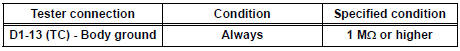
5 CHECK WIRE HARNESS (TC OF DLC3 - BODY GROUND)
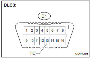
- Measure the resistance according to the value(s) in the table below.
Standard resistance
 REPAIR OR REPLACE WIRE
HARNESS OR
EACH ECU
REPAIR OR REPLACE WIRE
HARNESS OR
EACH ECU

REPLACE CENTER AIRBAG SENSOR ASSEMBLY
 SRS Warning Light does not Come ON
DESCRIPTION
WIRING DIAGRAM
INSPECTION PROCEDURE
1 CHECK BATTERY
Measure the voltage of the battery.
Standard voltage:
11 to 14 V
CHECK AND REPLACE BATTERY OR
CHARGING SYSTEM
2 CHECK CO ...

Other materials:
Installation
HINT:
Install the RH side by the same procedure as the LH side.
1. INSTALL REAR SPEED SENSOR
(a) Clean the contacting surface of the axle hub and a
new skid control sensor.
NOTICE:
Keep the sensor rotor clean.
(b) Place the speed sensor on the axle hub so that the
connector is positioned ...
How to proceed with
troubleshooting
1 VEHICLE BROUGHT TO WORKSHOP
2 CUSTOMER PROBLEM ANALYSIS
3 CHECK INITIAL CHECK FUNCTION
4 PROBLEM SYMPTOMS TABLE
THE CORRESPONDING SYSTEM DOES NOT EXIST (Go to step 5)
5 BASED ON THE MALFUNCTION SYMPTOM, PERFORM THE TROUBLESHOOTING
BELOW
Operation check (C).
Terminals of ECU
6 ...
Engine unit
COMPONENTS
...
