Toyota Sienna Service Manual: Diagnosis Circuit
DESCRIPTION
DTC output mode is set by connecting terminals TC and CG of the DLC3.
DTCs are displayed by blinking the SRS warning light.
HINT:
- When each warning light stays blinking, a ground short in the wiring of terminal TC of the DLC3 or an internal ground short in each ECU is suspected.
- A DTC output mode signal is transmitted through BEAN and CAN to each ECU including the center airbag sensor assembly. Thus when all systems do not enter DTC output mode, there may be an ECM malfunction.
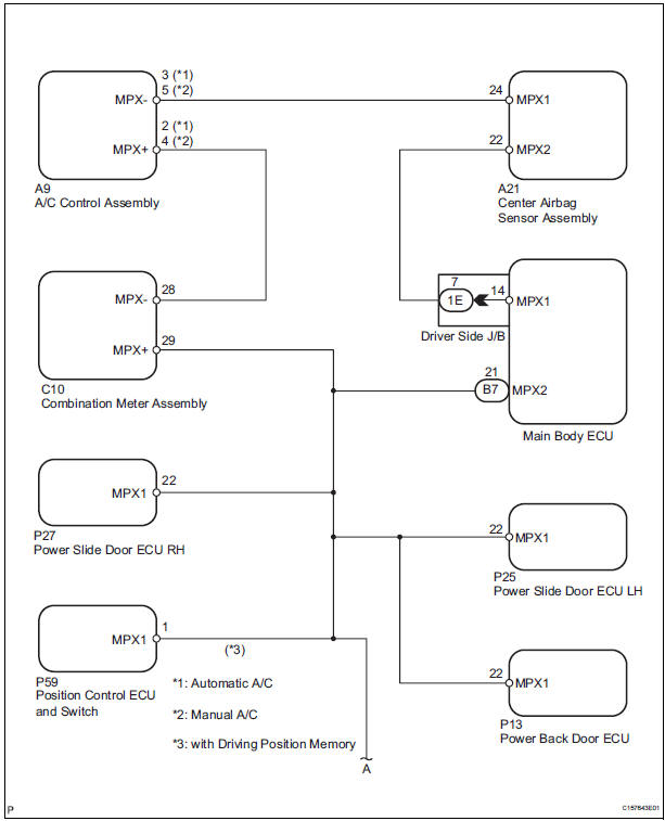
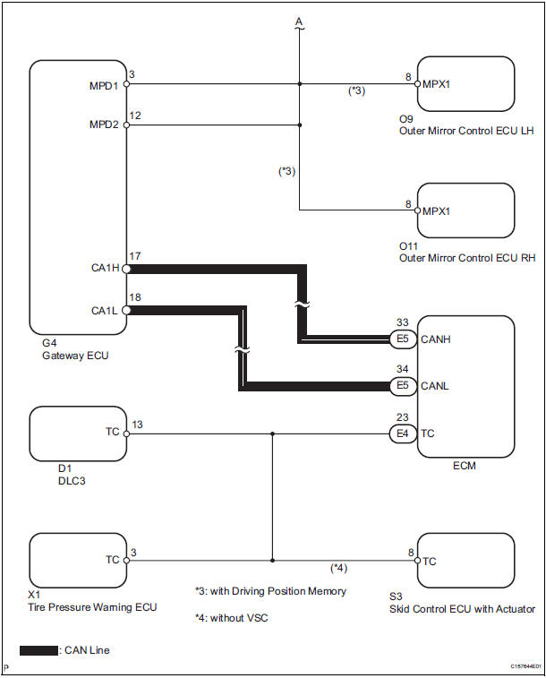
WIRING DIAGRAM
INSPECTION PROCEDURE
1 CHECK MULTIPLEX COMMUNICATION SYSTEM
- Check if the multiplex communication system DTC is output.
HINT: The center airbag sensor assembly of this system is connected to the multiplex communication system.
Therefore, before starting troubleshooting, make sure to check that there is no trouble in the multiplex communication system.
OK: The Multiplex communication system DTC is not output.
2 CHECK CAN COMMUNICATION SYSTEM
- Use the intelligent tester to check if the CAN communication system is functioning normally.
HINT: The ECM is connected to the CAN communication system. Therefore, before starting troubleshooting, make sure to check that there is no trouble in the CAN communication system.
OK: The CAN communication system is functioning normally.
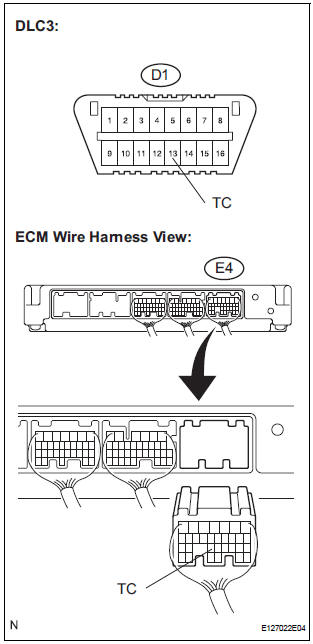
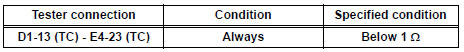
3 CHECK WIRE HARNESS (TC OF DLC3 - TC OF ECM)
- Turn the ignition switch to the LOCK position.
- Disconnect the connector from the ECM.
- Measure the resistance according to the value(s) in the table below.
Standard resistance
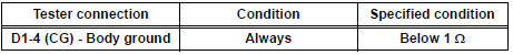
4 CHECK WIRE HARNESS (CG OF DLC3 - BODY GROUND)
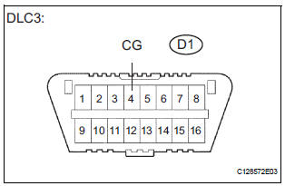
- Measure the resistance according to the value(s) in the table below.
Standard resistance
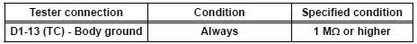
5 CHECK WIRE HARNESS (TC OF DLC3 - BODY GROUND)
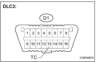
- Measure the resistance according to the value(s) in the table below.
Standard resistance
REPLACE CENTER AIRBAG SENSOR ASSEMBLY
 SRS Warning Light does not Come ON
DESCRIPTION
WIRING DIAGRAM
INSPECTION PROCEDURE
1 CHECK BATTERY
Measure the voltage of the battery.
Standard voltage:
11 to 14 V
2 CHECK CONNECTORS
Turn the ignition switch to the LOCK ...

Other materials:
Freeze frame data
1. FREEZE FRAME DATA
(a) The vehicle (sensor) status, stored during ABS and/
or VSC operation or at the time of an error code
detection, can be displayed by the intelligent tester.
(b) Only one record of freeze frame data is stored and
the freeze frame data generated during ABS and/or
VSC op ...
Installation
1. INSTALL OUTSIDE MOULDING
Using a heat light, heat the mounting surface of the
vehicle body between 40 to 60 C (104 to 140 F).
NOTICE:
Do not heat the body excessively.
Remove the tape from the vehicle body.
Wipe off the stains with cleaner.
Clean the outside moulding (if reusing t ...
Installation
1. INSTALL FRONT SEAT ASSEMBLY RH
Place the seat assembly in the cabin.
NOTICE:
Be careful not to damage the body.
Connect the connectors under the seat assembly.
Tighten the 2 bolts on the front side of the seat
assembly.
Torque: 37 N*m (375 kgf*cm, 27 ft.*lbf)
...
