Toyota Sienna Service Manual: Diagnosis system
1. DESCRIPTION
- Front power seat control system data can be read through the Data Link Connector 3 (DLC3) of the vehicle. When the system seems to be malfunctioning, use the intelligent tester to check for malfunctions and perform repairs.
2. CHECK DLC3
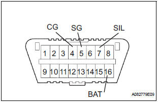
- The vehicle uses ISO 15765-4 communication protocol. The terminal arrangement of the DLC3 complies with SAE J1962 and matches the ISO 15765-4 format.
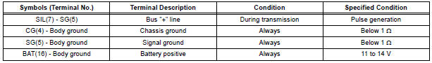
If the result is not as specified, the DLC3 may have a malfunction. Repair or replace the wire harness and connector.
HINT: Connect the cable of the intelligent tester to the DLC3, turn the ignition switch on and attempt to use the tester. If the screen displays a communication error message, a problem exists on the vehicle side or the tester side.
- If communication is normal when the tester is connected to another vehicle, inspect the DLC3 of the original vehicle.
- If communication is still not possible when the tester is connected to another vehicle, the problem is probably in the tester itself. Consult the Service Department listed in the tester's instruction manual.
3. INSPECT BATTERY VOLTAGE
- Check the battery voltage.
Voltage: 11 to 14 V
If the voltage is below 11 V, recharge or replace the battery before proceeding.
 Terminals of ECU
1. POSITION CONTROL ECU AND SWITCH ASSEMBLY
(POWER SEAT CONTROL SWITCH AND ECU)
Disconnect the P58 and P59 connectors.
Check the voltage of each terminal of the wire
harness sid ...
 Data list / active test
1. DATA LIST
HINT:
Using the intelligent tester's DATA LIST allows the status
of a switch, sensor, actuator and other items to be read
without removing any parts. Reading the DATA LIST
early in t ...
Other materials:
VC Output Circuit
DESCRIPTION
The ECM constantly uses 5 V from the battery voltages supplied to the +B
(BATT) terminal to operate the
microprocessor. The ECM also provides this power to the sensors through the VC
output circuit.
When the VC circuit is short-circuited, the microprocessor in the ECM and
sens ...
Problem symptoms table
HINT:
Use the table below to help determine the cause of the
problem symptoms. The potential causes of the symptoms
are listed in order of probability in the ''Suspected Area''
column of the table. Check each symptom by checking the
suspected areas in the order they are listed. Rep ...
Installation
1. INSTALL FRONT DOOR GLASS WEATHERSTRIP
Install the front door grass weatherstrip.
2. INSTALL OUTER REAR VIEW MIRROR ASSEMBLY
(See page MI-45)
3. INSTALL FRONT DOOR TRIM BOARD SUBASSEMBLY
4. INSTALL POWER WINDOW REGULATOR MASTER
SWITCH ASSEMBLY
5. INSTALL BACK FRAME PLATE
6. INSTALL FR ...
