Toyota Sienna Service Manual: Diagnostic trouble code chart
HINT:
The parameters listed in the chart may not confirm exactly to those read during the DTC check due to the type of instrument or other factors.
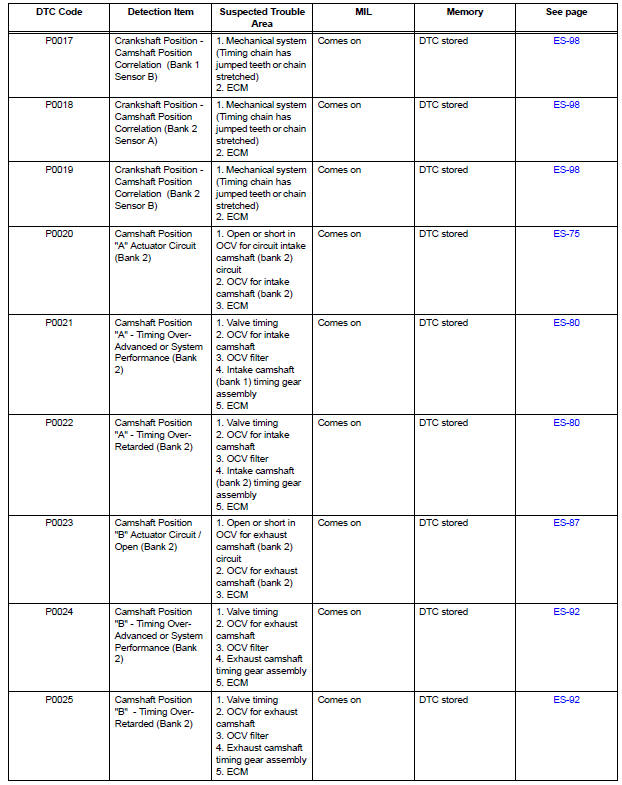
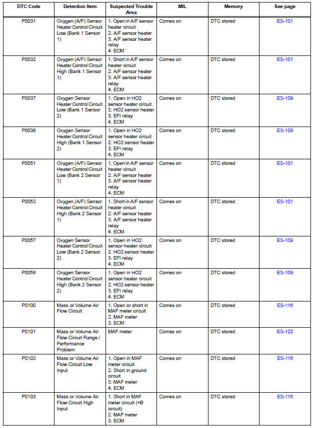
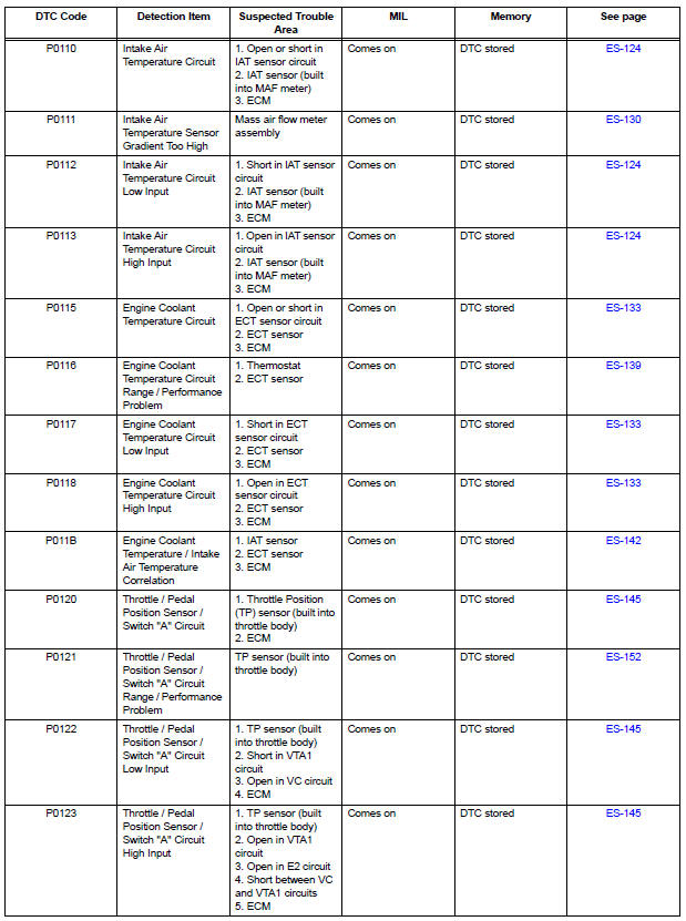
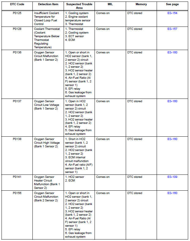
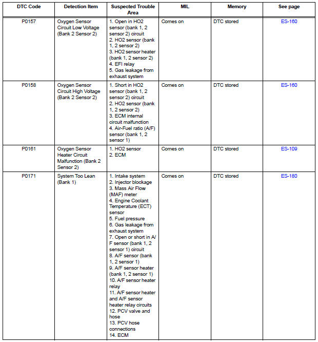
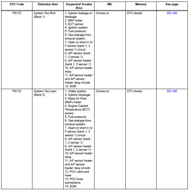
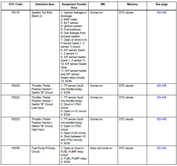
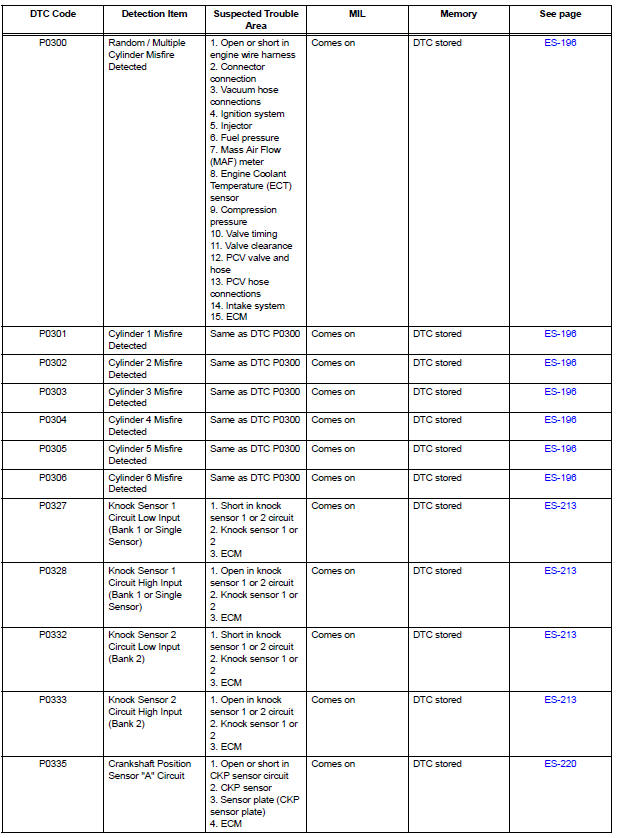
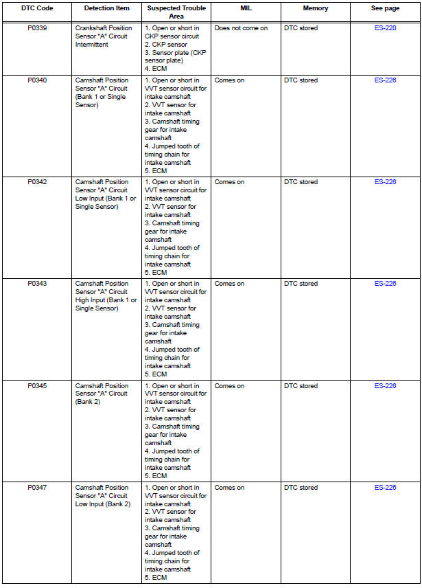
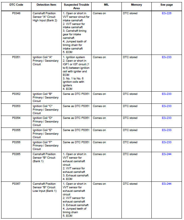
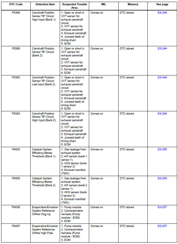
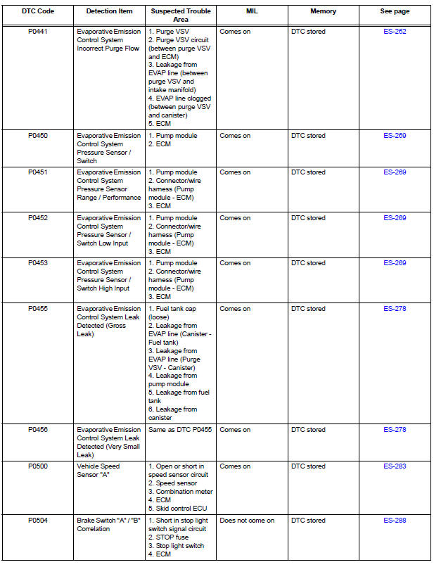
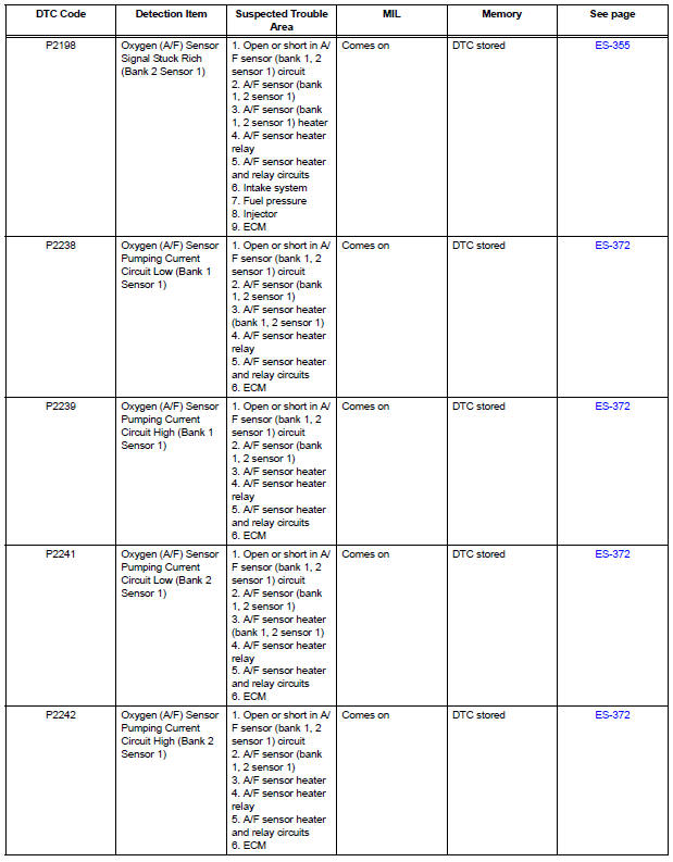
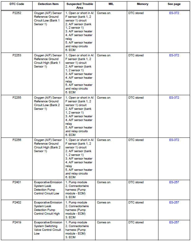
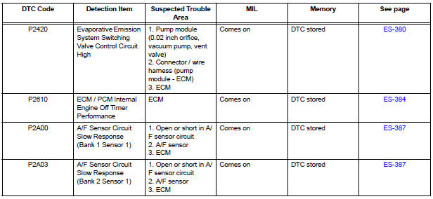
If a trouble code is displayed during the DTC check in the check mode, check the circuit for the code listed in the table below. For details of each code, refer to the "See page" column in the DTC chart.
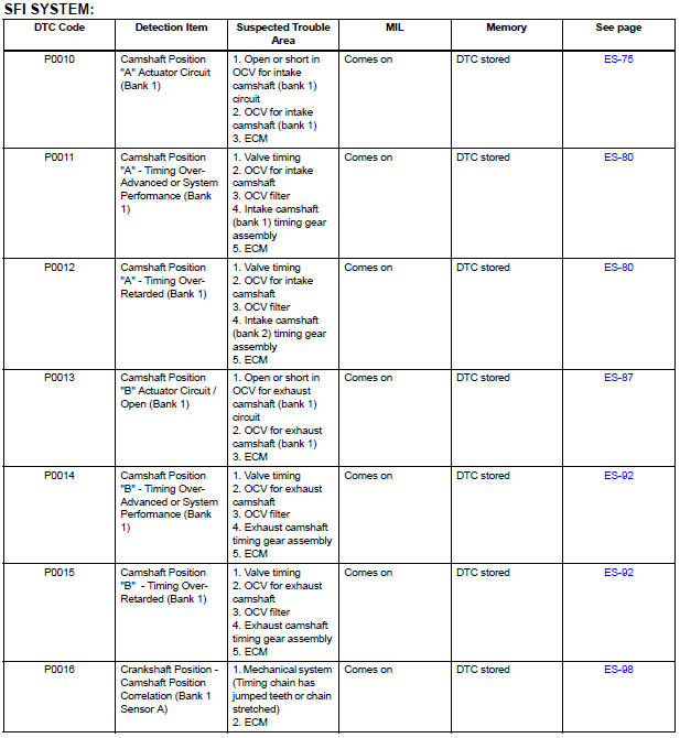
- Camshaft Position "A" Actuator Circuit
- Camshaft Position "A" - Timing Over
- Camshaft Position "B" Actuator Circuit
- Camshaft Position "B" - Timing Over
- Crankshaft Position - Camshaft Position Correlation
- Oxygen (A/F) Sensor Heater Control Circuit
- Oxygen Sensor Heater Control Circuit
- Mass or Volume Air Flow Circuit
- Mass or Volume Air Flow Circuit Range / Performance Problem
- Intake Air Temperature Circuit
- Intake Air Temperature Sensor Gradient Too High
- Engine Coolant Temperature Circuit
- Engine Coolant Temperature Circuit Range / Performance Problem
- Engine Coolant Temperature / Intake Air Temperature Correlation
- Throttle / Pedal Position Sensor / Switch "A"
- Throttle / Pedal Position Sensor / Switch "A" Circuit Range / Performance Problem
- Insufficient Coolant Temperature for Closed Loop Fuel Control
- Coolant Thermostat (Coolant Temperature Below Thermostat Regulating Temperature)
- Oxygen Sensor Circuit
- System Too
- Fuel Pump Primary Circuit
- Random / Multiple Cylinder Misfire Detected
- Knock Sensor 1 Circuit Low Input
- Crankshaft Position Sensor
- Camshaft Position Sensor "A" Circuit
- Ignition Coil "A" Primary
- Camshaft Position Sensor "B" Circuit
- Catalyst System Efficiency Below Threshold
- Evaporative Emission System Reference Orifice
- Evaporative Emission Control System Incorrect Purge Flow
- Evaporative Emission Control System Leak Detected
- Vehicle Speed Sensor "A"
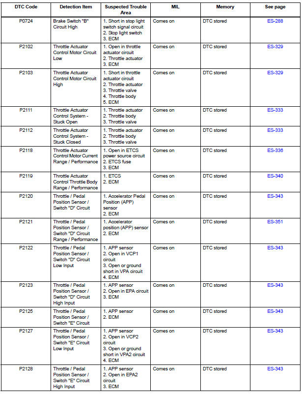
- Brake Switch
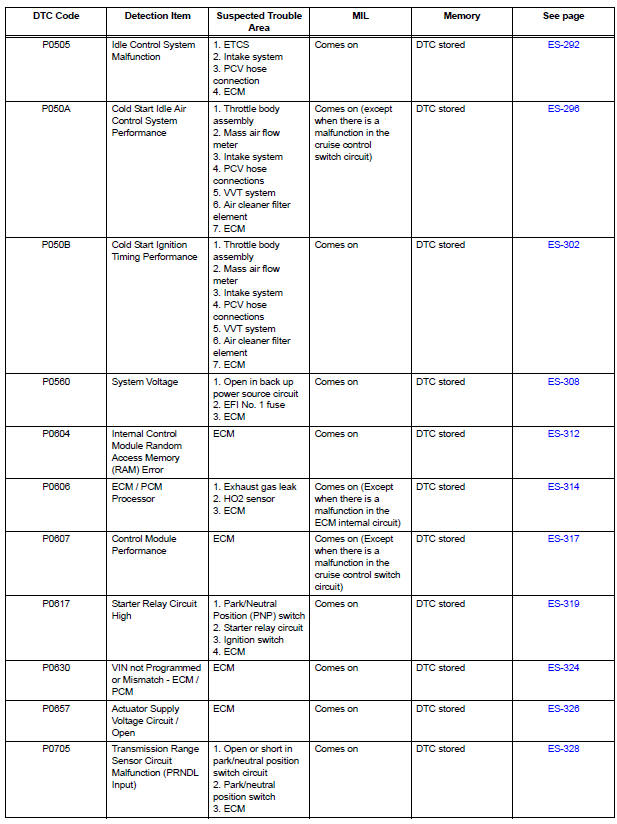
- Idle Control System Malfunction
- Cold Start Idle Air Control System Performance
- Cold Start Ignition Timing Performance
- System Voltage
- Internal Control Module Random Access Memory (RAM) Error
- ECM / PCM Processor
- Control Module Performance
- Starter Relay Circuit High
- VIN not Programmed or Mismatch - ECM / PCM
- Actuator Supply Voltage Circuit / Open
- Transmission Range Sensor Circuit Malfunction (PRNDL Input)
- Throttle Actuator Control Motor Circuit
- Throttle Actuator Control System
- Throttle Actuator Control Motor Current Range / Performance
- Throttle Actuator Control Throttle Body Range / Performance
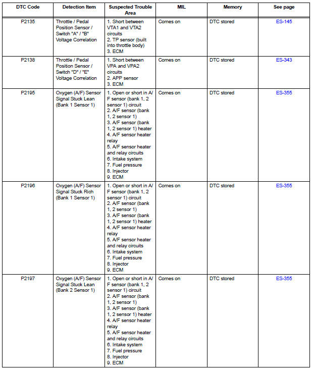
- Throttle / Pedal Position Sensor
- Throttle / Pedal Position Sensor / Switch "D" Circuit Range / Performance
- Oxygen (A/F) Sensor Signal Stuck
- Oxygen (A/F) Sensor Pumping Current Circuit
- Evaporative Emission System Switching Valve Control Circuit High
- ECM / PCM Internal Engine Off Timer Performance
- A/F Sensor Circuit Slow Response
- Active Control Engine Mount System
- EVAP System
- ECM Power Source Circuit
- VC Output Circuit
- Fuel Pump Control Circuit
- Cranking Holding Function Circuit
- ACIS Control Circuit
- Air Intake Control Circuit
- MIL Circuit
 System check
HINT:
Performing a SYSTEM CHECK enables the system,
which consists of the multiple actuators, to be operated
without removing any parts. In addition, it can show
whether or not any DTCs are set, a ...
 Camshaft Position "A" Actuator Circuit
DESCRIPTION
The Variable Valve Timing (VVT) system includes the ECM, Oil Control Valve
(OCV) and VVT controller.
The ECM sends a target duty-cycle control signal to the OCV. This control sig ...
Other materials:
Noise Occurs
INSPECTION PROCEDURE
1 NOISE CONDITION
Check in which direction the noise comes from (front left
or right, or rear left or right).
Check in which direction the noise comes from.
OK:
The location of the noise source can be
determined
2 CHECK SPEAKERS
Check the installatio ...
Dtc check / clear
1. DTC CHECK/CLEAR (WHEN USING INTELLIGENT TESTER):
(a) DTC check
(1) Connect the intelligent tester to the DLC3.
(2) Turn the ignition switch to the ON position.
(3) Read the DTCs following the prompts on the
tester screen.
(b) DTC clear
(1) Connect the intelligent tester to the DLC3 ...
Radio and Navigation Assembly Communication Error
INSPECTION PROCEDURE
1 IDENTIFY THE COMPONENT SHOWN BY THE SUB-CODE
Enter the diagnostic mode.
Press the "LAN Mon" switch to change to "LAN Monitor"
mode.
Identify the component shown by the sub-code.
HINT:
"110 (multi-display)" i ...
