Toyota Sienna Service Manual: Disassembly
1. Remove rear wheel
2. Drain brake fluid
Notice: wash the brake fluid off immediately if it attaches to any painted surface.
3. REMOVE REAR BRAKE DRUM SUB-ASSEMBLY
(a) Release the parking brake lever, and remove the rear brake drum.
HINT: If the rear brake drum cannot be removed easily, perform the following procedure.
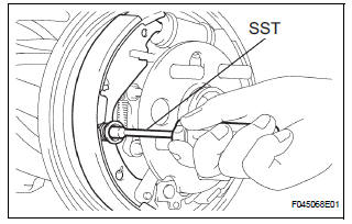
(b) Remove the hole plug and insert a screwdriver through the hole in the backing plate, and hold the automatic adjusting lever away from the adjuster.
(c) Using another screwdriver, reduce the brake shoe adjuster by turning the adjusting wheel.
4. REMOVE FRONT BRAKE SHOE
(a) Using SST, remove the shoe return spring from the front brake shoe.
SST 09921-00010
(b) Using a needle-nose pliers, remove the return spring.
(c) Using SST, remove the shoe hold down spring cup, shoe hold down spring and pin.
SST 09718-00010 (d) Remove the parking brake shoe strut LWR.
(e) Remove the tension spring and front brake shoe.
(f) Remove the automatic adjust lever spring and rear brake automatic adjust lever LH from the front brake shoe.
5. REMOVE REAR BRAKE SHOE
(a) Using SST, remove the shoe hold down spring cup, shoe hold down spring and pin.
SST 09718-00010
(b) Using a needle-nose pliers, disconnect the parking brake cable No. 3 and remove the rear brake shoe.
(c) Using a screwdriver, remove the 2 C-washers, parking brake shoe lever, parking brake reaction lever LH and rear brake strut set.
6. REMOVE LH, FRONT OR UPPER REAR WHEEL BRAKE CYLINDER ASSEMBLY
(a) Using SST, disconnect the brake tube, use a container to catch the brake fluid.
SST 09023-00101
(b) Remove the 2 bolts and rear wheel brake cylinder assembly.
7. REMOVE REAR WHEEL CYLINDER CUP KIT
(a) Remove the 2 cylinder dust boots from the rear wheel brake cylinder assembly.
(b) Remove the 2 pistons and compression spring.
(c) Remove the 2 wheel cylinder cups from each piston.
(d) Remove the bleeder plug cap and bleeder plug from the rear wheel brake cylinder assembly.
 Rear drum brake
Components
...
 Inspection
1. INSPECT BRAKE DRUM INSIDE DIAMETER
(a) Using a brake drum gauge or equivalent, measure
the inside diameter of the drum.
Standard inside diameter:
254.0 mm (10.00 in.)
Maximum inside diamet ...
Other materials:
Diagnostic trouble code chart
HINT:
The parameters listed in the chart may not confirm exactly to
those read during the DTC check due to the type of
instrument or other factors.
If a trouble code is displayed during the DTC check in the
check mode, check the circuit for the code listed in the table
below. For details of ...
ECM Power Source Circuit
DESCRIPTION
When the ignition switch is turned to the ON position, the battery voltage is
applied to terminal IGSW of
the ECM. The ECM MREL output signal causes a current to flow to the coil,
closing the contacts of the EFI
relay and supplying power to terminal +B of the ECM.
If the igniti ...
Removal
1. REMOVE BATTERY (See page EM-26)
2. REMOVE NO. 2 AIR CLEANER INLET (See page EM-
28)
3. REMOVE AIR CLEANER CAP SUB-ASSEMBLY (See
page FU-13)
4. REMOVE AIR CLEANER FILTER ELEMENT (See page
EM-28)
5. REMOVE AIR CLEANER CASE SUB-ASSEMBLY (See
page EM-28)
6. REMOVE AIR CLEANER BRACKET
(a ...
