Toyota Sienna Service Manual: Disassembly
1. HOLD VANE PUMP ASSEMBLY
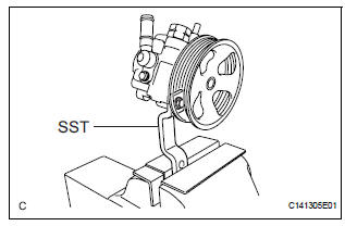
(a) Using SST, hold the vane pump assembly in a vise.
SST 09630-00014 (09631-00132)
2. REMOVE POWER STEERING SUCTION PORT UNION
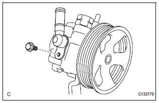
(a) Remove the bolt and the power steering suction port union from the vane pump front housing.
(b) Using a screwdriver, remove the O-ring from the power steering suction port union.
3. REMOVE POWER STEERING FLUID PRESSURE SWITCH
NOTICE: Perform this procedure only when the power steering fluid pressure switch is replaced.
(a) Remove the power steering fluid pressure switch from the vane pump front housing.
4. REMOVE FLOW CONTROL VALVE ASSEMBLY
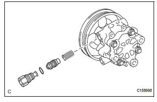
(a) Remove the pressure port union from the vane pump front housing.
(b) Remove the O-ring from the pressure port union.
(c) Remove the flow control valve assembly and the flow control valve compression spring from the vane pump front housing.
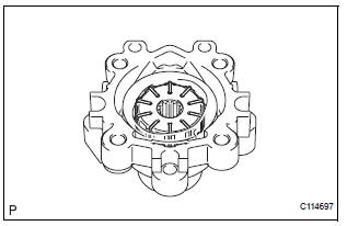
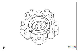
5. REMOVE VANE PUMP REAR HOUSING
(a) Remove the 4 bolts and vane pump rear housing from the vane pump front housing.
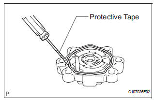
(b) Using a screwdriver, remove the O-ring from the vane pump rear housing.
HINT: Tape the screwdriver tip before use.
6. REMOVE VANE PUMP SHAFT WITH PULLEY
(a) Using 2 screwdrivers, remove the vane pump shaft snap ring from the vane pump shaft with pulley.
(b) Remove the vane pump shaft with pulley.
7. REMOVE VANE PUMP ROTOR
(a) Remove the 10 vane pump plates.
(b) Remove the vane pump rotor.
8. REMOVE VANE PUMP CAM RING
(a) Remove the vane pump cam ring from the vane pump front housing.
9. REMOVE VANE PUMP FRONT SIDE PLATE
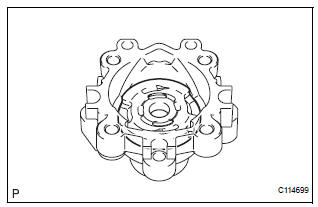
(a) Remove the vane pump front side plate from the vane pump front housing.
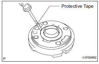
(b) Using a screwdriver, remove the O-ring from the vane pump front side plate.
HINT: Tape the screwdriver tip before use.
(c) Remove the O-ring from the vane pump front housing.
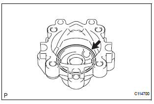
10. REMOVE VANE PUMP HOUSING OIL SEAL
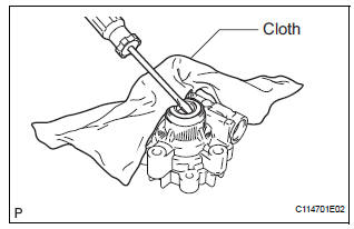
(a) Using a screwdriver and a shop rag or a piece of cloth, remove the vane pump housing oil seal from the vane pump front housing.
NOTICE: Be careful not to damage the vane pump front housing.
 Removal
1. DRAIN POWER STEERING FLUID
2. REMOVE FRONT WHEEL RH
3. REMOVE FRONT FENDER APRON SEAL RH (See
page EM-26)
4. REMOVE FAN AND GENERATOR V BELT (See page
EM-6)
5. DISCONNECT NO. 1 FLUID RESERVOI ...
 Inspection
1. INSPECT VANE PUMP SHAFT AND BUSHING IN VANE PUMP FRONT HOUSING
(a) Using a micrometer, measure the outer diameter [a]
of the vane pump shaft with pulley.
(b) Using vernier calipers, measur ...
Other materials:
CD Changer Mechanical Error/ CD Insertion and Ejection Error/ CD Reading
Abnormal
DTC 63-10 CD Changer Mechanical Error
DTC 63-11 CD Insertion and Ejection Error
DTC 63-12 CD Reading Abnormal
DESCRIPTION
DTC No.
DTC Detection Condition
Trouble Area
63-10
A mechanical error in the CD changer is detected while
the CD is not being inserted ...
Rear Air Conditioning Relay Circuit
DESCRIPTION
The RR A/C relay is switched on by signals from the A/C amplifier. It
supplies power to the rear blower
motor.
WIRING DIAGRAM
INSPECTION PROCEDURE
1 INSPECT RELAY (RR A/C)
(a) Remove the RR A/C relay from the No. 3 relay block.
(b) Measure the resistance according to t ...
Terminals of ECU
1. CHECK POWER SLIDE DOOR ECU LH
Disconnect the P25 and P26 ECU connectors, and
check the voltage and resistance of each terminal of
the wire harness side connectors
If the result is not as specified, there may be a
malfunction on the wire harness side.
Reconnect the EC ...
