Toyota Sienna Service Manual: Disassembly
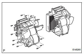
1. REMOVE BLOWER ASSEMBLY
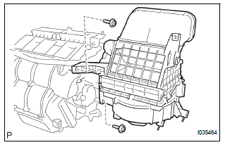
(a) Remove the 2 screws and the blower assembly.
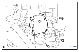
2. REMOVE MODE DAMPER SERVO SUB-ASSEMBLY
(a) Remove the 3 screws and the mode damper servo sub-assembly.
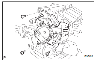
3. REMOVE AIRMIX DAMPER SERVO SUB-ASSEMBLY
(a) Remove the 3 screws and the airmix damper servo sub-assembly.
4. REMOVE NO. 2 AIRMIX DAMPER SERVO SUBASSEMBLY (for Automatic Air Conditioning System)
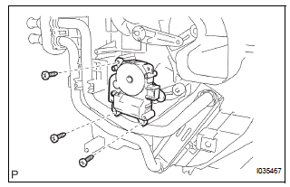
(a) Remove the 3 screws and the No. 2 airmix damper servo sub-assembly.
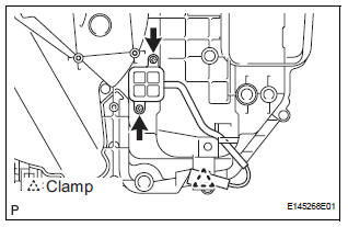
5. REMOVE NO. 1 HEATER CLAMP
(a) Release the 4 claw fittings and remove the No. 1 heater clamp.
6. REMOVE NO. 3 AIR CONDITIONING RADIATOR BRACKET
(a) Remove the screw and the No. 3 air conditioning radiator bracket.
7. REMOVE HEATER RADIATOR UNIT SUB-ASSEMBLY
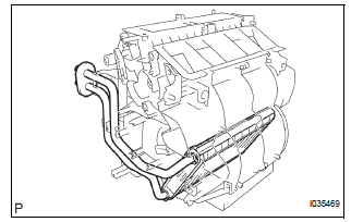
(a) Remove the heater radiator unit sub-assembly from the air conditioning radiator assembly.
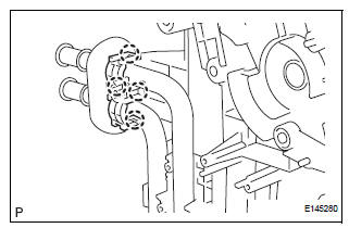
8. REMOVE AIR CONDITIONING TUBE ASSEMBLY
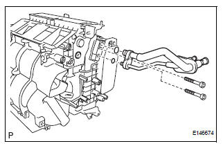
(a) Using a hexagon wrench 4.0 mm (0.15 in.), remove the 2 hexagon bolts and the air conditioning tube assembly.
(b) Remove the 2 O-rings from the air conditioning tube assembly.
9. REMOVE COOLER EXPANSION VALVE
(a) Remove the cooler expansion valve from the No. 1 cooler evaporator sub-assembly.
(b) Remove the 2 O-rings from the No. 1 cooler evaporator sub-assembly.
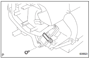
10. REMOVE NO. 2 AIR CONDITIONING RADIATOR BRACKET
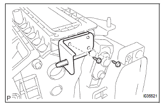
(a) Remove the 2 screws and the No. 2 air conditioning radiator bracket.
11. REMOVE NO. 1 AIR CONDITIONING RADIATOR BRACKET
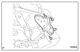
(a) Remove the 3 screws and the No .1 air conditioning radiator bracket.
12. REMOVE NO. 4 AIR CONDITIONING RADIATOR BRACKET
(a) Remove the No. 4 air conditioning radiator bracket.
13. REMOVE NO. 1 AIR DUCT
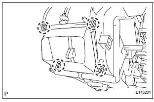
(a) Release the 4 claw fittings and remove the No. 1 air duct.
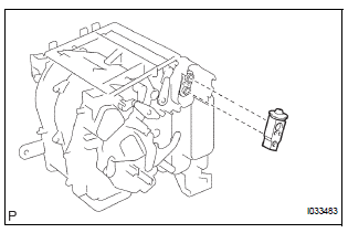
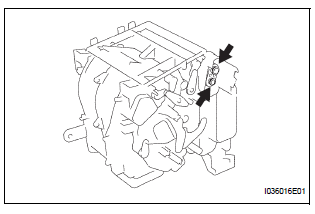
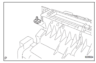
14. REMOVE NO. 1 COOLER THERMISTOR
(a) Disengage the clamp.
(b) Remove the 2 screws.
(c) Remove the 11 screws.
(d) Remove the No. 1 cooler thermistor.
 Removal
1. RECOVER REFRIGERANT FROM REFRIGERATION
SYSTEM (See page AC-172)
2. REMOVE FRONT WIPER ARM HEAD CAP (See page
WW-4)
3. REMOVE FRONT WIPER ARM RH (See page WW-4)
4. REMOVE FRONT WIPER ARM LH (Se ...
 Reassembly
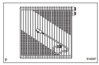
1. INSTALL NO. 1 COOLER THERMISTOR
(a) Install the No. 1 cooler thermistor as shown in the
illustration.
NOTICE:
Be sure to insert the thermistor only once
because reinserting it will no ...
Other materials:
Removal
1. REMOVE INSTRUMENT CLUSTER FINISH PANEL
CENTER NO.1 (See page IP-8)
2. REMOVE INSTRUMENT CLUSTER FINISH PANEL
CENTER NO.2
3. REMOVE SHIFT LEVER KNOB SUB-ASSEMBLY
HINT:
(See page AX-146 for U151E, AX-146 for U151F)
4. REMOVE INSTRUMENT CLUSTER FINISH PANEL
ASSEMBLY CENTER (See page IP-9)
5 ...
Inspection
1. INSPECT CAMSHAFT TIMING OIL CONTROL VALVE ASSEMBLY
Resistance inspection
Using an ohmmeter, measure the resistance
between the terminals.
Resistance:
6.9 to 7.9 Ω at 20C (68F)
If necessary, replace the camshaft timing oil
control valve assembly.
&nbs ...
Improper Aiming of Radar Sensor Beam Axis
DTC P1572 Improper Aiming of Radar Sensor Beam Axis
DESCRIPTION
This DTC is output when the scanning angle of the laser sensor is incorrect.
This DTC is also output when
the laser sensor beam axis is determined to be in an incorrect position.
DTC No.
DTC Detection Condition
...
