Toyota Sienna Service Manual: Disassembly
1. REMOVE COOLER THERMISTOR NO.1 (for Automatic Air Conditioning System)
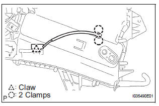
(a) Disengage the 2 claw fittings and the clamp and remove the cooler thermistor No. 1.
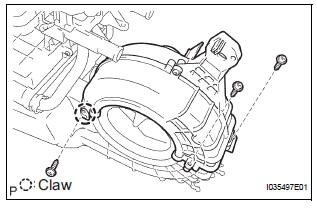
2. REMOVE COOLING UNIT MOTOR SUB-ASSEMBLY WITH FAN
(a) Remove the 3 screws and the cooling unit motor sub-assembly w/ fan.
3. REMOVE BLOWER RESISTOR TRANSISTOR ASSEMBLY
(a) Remove the 2 screws and the blower resistor transistor assembly.
4. REMOVE HEATER RADIATOR UNIT SUB-ASSEMBLY
(a) Disengage the claw fitting and remove the 3 screws and blower case.
(b) Remove the 2 screws and the 2 clamps.
(c) Remove the 3 screws and the heater water valve assembly.
(d) Remove the 2 O-rings from the heater water valve assembly.
(e) Remove the heater radiator unit sub-assembly from the air conditioning blower assembly.
 Removal
1. DISCHARGE REFRIGERANT FROM
REFRIGERATION SYSTEM
SST 07110-58060 (07117-58080, 07117-58090,
07117-78050, 07117-88060, 07117-88070,
07117-88080)
HINT:
See page AC-172.
2. REMOVE REAR DOOR SCUF ...
 Reassembly
1. INSTALL HEATER RADIATOR UNIT SUB-ASSEMBLY
(a) Install the heater radiator unit sub-assembly to the
air conditioning blower assembly.
(b) Install the 2 O-rings to the heater water valve
as ...
Other materials:
Definition of terms
Term
Definition
Monitor description
Description of what the ecm monitors and how it detects malfunctions
(monitoring purpose and its details).
Related dtcs
Diagnostic codeV
Typical enabling condition
Preconditions that allow the ecm to detect malfunc ...
Air Outlet Damper Control Servo Motor Circuit
DESCRIPTION
This circuit turns the servo motor and changes each damper position by
receiving the signals from the A/
C amplifier.
The air outlet damper servo motor switches the air outlet mode by rotating
(normal, reverse) with electrical
power from the A/C amplifier.
When the AUTO swit ...
Removal
1. REMOVE ENGINE AND TRANSAXLE
HINT:
(See page EM-26)
2. REMOVE AUTOMATIC TRANSMISSION WITH
TRANSFER
HINT:
(See page AX-164)
3. REMOVE NO. 1 TRANSFER CASE PLUG
(a) Remove the No. 1 transfer case plug.
(b) Remove the No. 1 gasket from the transfer case No.
1 plug.
4. REMOVE NO. 2 T ...
