Toyota Sienna Service Manual: Disassembly
1. REMOVE MAGNETIC CLUTCH ASSEMBLY
(a) Place the compressor and magnetic clutch in a vise.
(b) Using locking pliers, hold the magnetic clutch hub.
(c) Remove the bolt, magnetic clutch hub, and magnetic clutch washers.
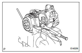
HINT: There is no set number of magnetic clutch washers because they are used for adjustment.
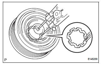
(d) Using a snap ring expander, remove the snap ring and magnetic clutch rotor.
NOTICE: Take care not to damage the seal cover of the bearing when removing the snap ring.
(e) Remove the screw and disconnect the connector.
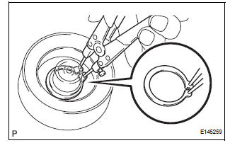
(f) Using a snap ring expander, remove the snap ring and magnetic clutch stator.
 Removal
1. RECOVER REFRIGERANT FROM REFRIGERATION
SYSTEM (See page AC-172)
2. REMOVE FRONT WHEEL RH
3. REMOVE FRONT FENDER APRON SEAL RH (See
page EM-26)
4. REMOVE V-RIBBED BELT (See page EM-6)
5. REMOV ...
 Inspection
1. INSPECT MAGNETIC CLUTCH CLEARANCE
(a) Set the dial indicator to the magnetic clutch hub.
(b) Connect the battery positive lead to the terminal 1 of
the magnet clutch connector and the nega ...
Other materials:
2Gr-fe engine mechanical
SERVICE DATA
TORQUE SPECIFICATIONS
2GR-FE FUEL
SERVICE DATA
TORQUE SPECIFICATIONS
2GR-FE EMISSION CONTROL
SERVICE DATA
TORQUE SPECIFICATIONS
2GR-FE INTAKE
SERVICE DATA
TORQUE SPECIFICATIONS
2GR-FE EXHAUST
SERVICE DATA
TORQUE SPECIFICAT ...
Power back door system
PARTS LOCATION
...
Key Lock-in Prevention Function does not Work Properly (Manual
Operation and Operation Interlocked with Key are Active)
DESCRIPTION
The un-lock warning switch turns ON when the key is inserted in the ignition
key cylinder. The courtesy
light switch turns ON when the driver side door is opened. These 2 switches are
monitored by the body
ECU.
In order to prevent the key from being locked in, the body ECU cont ...
