Toyota Sienna Service Manual: Disassembly
1. REMOVE REAR SEAT LEG COVER LH
- Remove the 2 screws and seat leg cover.
2. REMOVE REAR SEAT LEG COVER RH
- Remove the 2 screws and seat leg cover.
3. REMOVE REAR SEAT LEG SIDE COVER LH
- Remove the 2 screws and seat leg side cover.
4. REMOVE LH SEAT REAR SEAT LOCK COVER
- Remove the 2 screws and seat lock cover.
5. REMOVE RH SEAT REAR SEAT LOCK COVER
- Remove the 2 screws and seat lock cover.
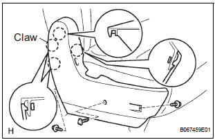
6. REMOVE RECLINING ADJUSTER INSIDE COVER LH
- Remove the 3 screws.
- Using a screwdriver, disengage the claws and remove the reclining adjuster inside cover.
HINT: Tape the screwdriver tip before use.
7. REMOVE RECLINING ADJUSTER COVER RH
- Remove the 3 screws.
- Using a screwdriver, disengage the claws and remove the reclining adjuster cover.
HINT: Tape the screwdriver tip before use.
8. REMOVE REAR SEAT LAP TYPE BELT ASSEMBLY CENTER
- Remove the bolt and lap type belt.
9. REMOVE FOLD SEAT STOPPER BAND ASSEMBLY
- Remove the screw and fold seat stopper band.
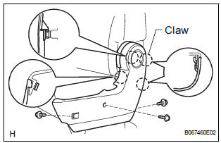
10. REMOVE REAR SEATBACK BOARD
- Remove the rear seatback board cap.
- Remove the 2 screws.
- Remove the seatback board by pulling it out in the arrow mark direction shown in the illustration.
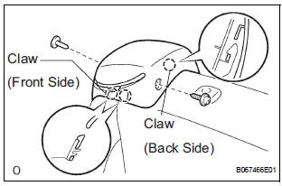
11. REMOVE REAR SEATBACK LOCK BEZEL UPPER
- Remove the clip and screw.
- Using a screwdriver, disengage the front side claws.
HINT: Tape the screwdriver tip before use.
- Apply firm pressure in the directions shown to disengage back side claw and remove the seatback lock bezel upper.
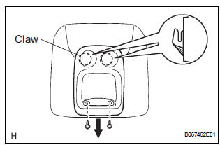
12. REMOVE REAR SEATBACK COVER
- Disengage the claw, and remove the 2 headrest supports.
- Remove the hog rings and seatback cover together with the pad.
- Remove the hog rings and seatback cover.
13. REMOVE NO. 1 SEAT CUSHION COVER SUBASSEMBLY
- Remove the hog rings between seat cushion cover and cushion frame wire and remove the seat cushion cover together with the pad.
- Remove the hog rings between the seat cushion cover and the pad.
14. REMOVE REAR SEAT SHOULDER BELT COVER RH
- Remove the 2 screws and seat shoulder belt cover.
15. REMOVE NO. 1 SEATBACK FRAME SUB-ASSEMBLY
- Remove the screw and seatback hinge cover.
- Remove the nut and seat belt retractor.
- Remove the 4 bolts and seatback frame.
16. REMOVE REAR SEAT HINGE COVER LH
- Remove the screw and seat hinge cover.
17. REMOVE REAR SEAT HINGE COVER
- Remove the screw and seat hinge cover.
18. REMOVE REAR SEAT RECLINING ADJUSTER ASSEMBLY LH
- Disengage the reclining remote control cable.
- Remove the 3 bolts and seat reclining adjuster.
19. REMOVE RECLINING CONNECTING PIPE
20. REMOVE NO. 1 REAR SEAT BELT ASSEMBLY OUTER RH
- Remove the 3 nuts and seat belt reclining sensor together with the seat belt.
21. REMOVE REAR SEAT RECLINING ADJUSTER ASSEMBLY RH
- Remove the 2 bolts and seat reclining adjuster.
22. REMOVE REAR SEAT TRACK ADJUSTING HANDLE
- Using a screwdriver, disengage the pin and remove seat track adjusting handle.
HINT: Tape the screwdriver tip before use.
23. REMOVE RECLINING CONTROL LINK SUBASSEMBLY
- Remove the nut.
- Remove the E-ring and reclining control link.
24. REMOVE NO. 1 SEAT CUSHION FRAME SUBASSEMBLY
- Remove the 4 bolts and seat cushion frame.
 Components
REMOVAL
1. REMOVE REAR NO. 1 SEAT ASSEMBLY CENTER
Remove the headrest.
Remove the bolt and seat belt anchor plate.
Remove the rear seat.
...
 Reassembly
1. INSTALL NO. 1 SEAT CUSHION FRAME SUBASSEMBLY
Install the seat cushion frame with the bolt.
Torque: 20.6 N*m (210 kgf*cm, 15 ft.*lbf)
2. INSTALL RECLINING CONTROL LINK SUBASSEMBLY
...
Other materials:
System description
1. BRIEF DESCRIPTION
The CAN (Controller Area Network) is a serial data
communication system for real time application. It is
a vehicle multiplex communication system which
has a high communication speed (500 kbps) and
the ability to detect malfunctions.
By pairing the CANH and CANL bu ...
Fuel Pump Primary Circuit
DESCRIPTION
This DTC is designed to detect a malfunction in the fuel pump (FUEL
PUMP) relay circuit. When the
system is normal, the battery voltage is applied to FPR terminal of the ECM
while the FUEL PUMP
relay is turned OFF. If the battery voltage is not applied to the FPR
ter ...
If you have a flat tire
(vehicles with
run-flat tires)
Your vehicle is not equipped with a spare tire, but instead you
can continue driving the vehicle with run-flat tires even if any
tire goes flat.
In this case, slow down and drive with extra caution.
Run-flat tires (A “RFT” or “DSST” mark is molded on the sidewall)
Take your vehicle to ...
