Toyota Sienna Service Manual: Disassembly
HINT: On the RH side, use the same procedures as on the LH side.
1. REMOVE FRONT DOOR LOWER FRAME BRACKET GARNISH LH
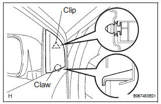
- Using a screwdriver, disengage the clip and claw, and remove the garnish.
HINT: Tape the screwdriver tip before use.
2. REMOVE FRONT DOOR INSIDE HANDLE BEZEL PLUG LH
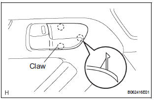
- Using a screwdriver, disengage the 3 claws and remove the bezel.
HINT: Tape the screwdriver tip before use
3. REMOVE POWER WINDOW REGULATOR MASTER SWITCH ASSEMBLY
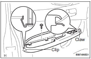
- Remove the screw.
- Using a screwdriver, disengage the clip and claw,
and remove the armrest base panel upper together
with the switch.
HINT: Tape the screwdriver tip before use.
- Disconnect the connector.
- Remove the 3 screws and switch from the armrest base panel upper.
- Using pliers, remove the 2 pins and armrest.
4. REMOVE FRONT DOOR TRIM BOARD SUBASSEMBLY LH
- Remove the 3 screws and back frame plate.
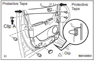
- Remove the 2 cushion rubbers.
- Remove the 2 screws and the clip A.
- Using a screwdriver, disengage the other 9 clips.
HINT: Tape the screwdriver tip before use.
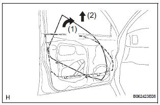
- Remove the trim board upward.
HINT: In order to prevent the door panel from being damaged, cover the areas indicated by arrow marks in the illustration with protective tape.
- Disconnect the 2 cables from the inside handle, as shown in the illustration.
- Using a screwdriver, disengage the 10 hooks and
remove the weatherstrip inner.
HINT: Tape the screwdriver tip before use.
- Remove the 2 screws and inside handle.
5. REMOVE FRONT DOOR SERVICE HOLE COVER LH
- Remove the screw and reinforcement No. 1.
- Remove the service hole cover.
NOTICE: Remove the tape remaining on the door side.
6. REMOVE OUTER REAR VIEW MIRROR ASSEMBLY LH
- Disconnect the connector.
- Remove the 3 nuts and mirror.
NOTICE: When the nuts are removed, the mirror assembly may fall and become deformed.
7. REMOVE FRONT NO.1 SPEAKER ASSEMBLY (See page AV-206)
8. REMOVE FRONT DOOR WINDOW FRAME MOULDING REAR LH (See page ET-30)
9. REMOVE FRONT DOOR GLASS WEATHERSTRIP ASSEMBLY OUTER LH (See page ET-21)
10. REMOVE FRONT DOOR GLASS SUB-ASSEMBLY LH
HINT: Insert a shop rag inside the door panel to prevent the door glass from being scratched.
- Open the door glass until the bolts appear in the service holes.
- Remove the 2 bolts holding the door glass to the window regulator.
- Remove the door glass in the direction indicated by the arrow mark in the illustration.
NOTICE:
- Do not damage the door glass.
- When the bolts are removed, the door glass may fall and become deformed.
- Remove the glass run.
11. REMOVE FRONT DOOR WINDOW REGULATOR SUB-ASSEMBLY LH
- Disconnect the window regulator connector.
- Remove the 6 bolts and window regulator.
NOTICE: When the bolts are removed, the window regulator sub-assembly may fall and become deformed.
HINT: Remove the window regulator through the service hole.
12. REMOVE POWER WINDOW REGULATOR MOTOR ASSEMBLY LH
- Using a torx driver (T25), remove the 3 screws and window regulator motor.
13. REMOVE FRONT DOOR FRAME SUB-ASSEMBLY REAR LOWER LH
- Remove the bolt and frame.
14. REMOVE FRONT DOOR OUTSIDE HANDLE COVER
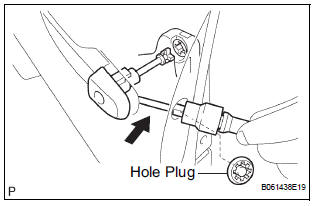
- Remove the hole plug.
- Using a torx socket wrench (T30), loosen the screw and remove the outside handle cover with the door lock key cylinder installed.
15. REMOVE FRONT DOOR WITH MOTOR LOCK ASSEMBLY LH
- Disconnect the door lock connector.
- Using a torx socket wrench (T30), remove the 3 screws and lock.
HINT: Remove the door lock through the service hole.
16. REMOVE FRONT DOOR HANDLE ASSEMBLY OUTSIDE LH
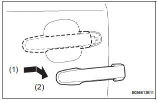
- Pushing and pulling the outside handle in the direction indicated by the arrow mark in the illustration, remove the outside handle.
- Remove the outside handle pads front and rear.
17. REMOVE FRONT DOOR OUTSIDE HANDLE FRAME SUB-ASSEMBLY LH
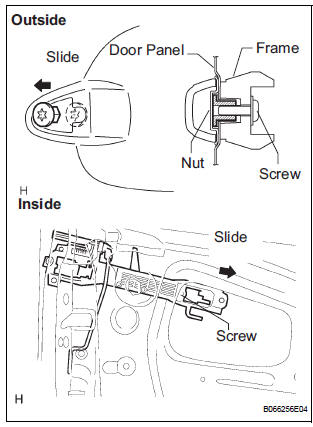
- Using a torx socket wrench (T30), loosen the screw.
- Slide the outside handle frame in the direction
indicated by the arrow mark in the illustration, and
remove it.
HINT: Remove the outside handle frame through the service hole.
- Remove the open rod from the outside handle frame.
18. REMOVE FRONT DOOR CHECK ASSEMBLY LH

- Remove the 2 nuts, bolt and door check.
19. REMOVE FRONT DOOR WEATHERSTRIP LH
- Using a clip remover, disengage the clips and remove the weatherstrip.
HINT: If the clips are damaged, replace them with new ones.
20. REMOVE FRONT DOOR WIRE LH
- Disconnect the wire clips.
- Remove the 2 bolts and wire.
 Front door
COMPONENTS
...
 Adjustment
HINT:
On the RH side, use the same procedures as on the LH
side.
Since a centering bolt is used as a door hinge mounting
bolt on the body side and the door side, the door can not
be adjust ...
Other materials:
General information
A large number of ECU controlled systems are used in the
SIENNA. In general, ECU controlled systems are considered
to be very intricate, requiring a high level of technical
knowledge to troubleshoot. However, most problem checking
procedures only involve inspecting the ECU controlled
system's c ...
Actuator Supply Voltage Circuit / Open
DESCRIPTION
The ECM monitors the output voltage to the throttle actuator. This self-check
ensures that the ECM is
functioning properly. The output voltage is usually 0 V when the ignition switch
is turned off. If the output
voltage is higher than 7 volts when the ignition switch is turned ...
How to proceed with
troubleshooting
HINT:
Troubleshoot in accordance with the procedures on the
following pages.
1 VEHICLE BROUGHT TO WORKSHOP
2 CUSTOMER PROBLEM ANALYSIS CHECK AND SYMPTOM CHECK
3 PROBLEM SYMPTOMS TABLE
When problem is not listed on problem symptoms table,
proceed to A.
When problem is listed on pro ...
