Toyota Sienna Service Manual: Disassembly
1. INSPECT OIL PUMP ASSEMBLY
HINT: (See page AX-234)
2. REMOVE CLUTCH DRUM OIL SEAL RING

(a) Remove the 2 clutch drum oil seal rings.
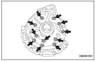
3. REMOVE STATOR SHAFT ASSEMBLY
(a) Using a "torx" socket (T30), remove the 11 bolts and stator shaft.
4. INSPECT CLEARANCE OF OIL PUMP ASSEMBLY
HINT: (See page AX-234)
5. REMOVE FRONT OIL PUMP DRIVE GEAR

(a) Remove the front oil pump drive gear.
6. REMOVE FRONT OIL PUMP DRIVEN GEAR
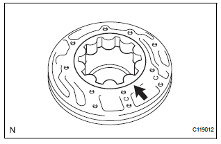
(a) Remove the front oil pump driven gear.
7. REMOVE FRONT OIL PUMP BODY O-RING
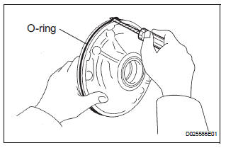
(a) Using a screwdriver, remove the O-ring.
HINT: Tape the screwdriver before use.
8. REMOVE FRONT OIL PUMP OIL SEAL
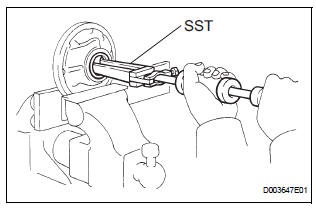
(a) Mount the oil pump in a soft jaw vise.
(b) Using SST, remove the oil seal from the oil pump body.
SST 09308-00010
 Oil pump
COMPONENTS
...
 Inspection
1. INSPECT OIL PUMP ASSEMBLY
(a) Turn the drive gear with the 2 screwdrivers and
make sure that it rotates smoothly.
NOTICE:
Be careful not to damage the oil seal lip.
2. INSPEC ...
Other materials:
On-vehicle inspection
1. CHECK SEAT HEATER CONTROL (WIRE HARNESS
SIDE)
Disconnect the connector from the seat heater
control.
Measure the voltage and resistance of each
terminal of the wire harness side connector.
Standard
If the result is not as specified, there may be a
malfunction on ...
Open in Front Passenger Side Squib Circuit
DTC B0106/54 Open in Front Passenger Side Squib Circuit
DESCRIPTION
The front passenger side squib circuit consists of the center airbag sensor
assembly and the front
passenger airbag assembly.
The circuit instructs the SRS to deploy when deployment conditions are met.
DTC B0106/54 is rec ...
Disassembly
1. INSPECT PACK CLEARANCE OF REVERSE CLUTCH
HINT:
(See page AX-249)
2. INSPECT PACK CLEARANCE OF DIRECT CLUTCH
AND OVERDRIVE CLUTCH
HINT:
(See page AX-249)
3. REMOVE DIRECT MULTIPLE DISC CLUTCH DISC
(a) Using a screwdriver, remove the snap ring from the
intermediate shaft.
(b) Remo ...
