Toyota Sienna Service Manual: Disassembly
1. INSPECT PACK CLEARANCE OF FORWARD CLUTCH
HINT: (See page AX-242)
2. REMOVE FORWARD MULTIPLE DISC CLUTCH DISC
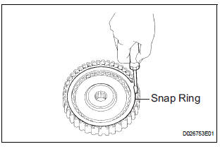
(a) Using a screwdriver, remove the snap ring.
(b) Remove the flange, 5 discs and 5 plates from the input shaft assembly.
3. REMOVE FORWARD CLUTCH RETURN SPRING SUB-ASSEMBLY
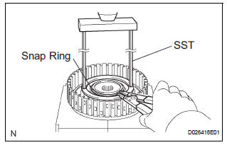
(a) Place SST on the spring retainer and compress the return spring with a press.
(b) Using a snap ring expander, remove the snap ring.
NOTICE:
- Stop the press when the spring seat is lowered 1 to 2 mm (0.039 to 0.078 in.) from the snap ring groove, preventing the spring seat from being deformed.
- Do not expand the snap ring excessively.
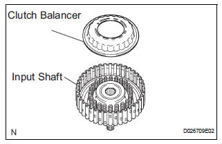
(c) Remove the clutch balancer from the input shaft.
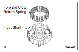
(d) Remove the forward clutch return spring from the input shaft.
4. REMOVE FORWARD CLUTCH RETURN SPRING SUB-ASSEMBLY
(a) Place the forward clutch drum onto the oil pump.
(b) Holding the forward clutch piston by hand, apply compressed air (392 kPa, 4.0 kgf/cm2, 57 psi) to the oil pump to remove the forward clutch piston.
HINT:
When the piston cannot be removed as it is slanted, blow air again with the protruding side pushed, or remove the piston using the needle nose pliers with vinyl tape on the tip.
5. REMOVE INPUT SHAFT OIL SEAL RING
(a) Remove the input shaft oil seal ring from the input shaft.
 Forward clutch
Components
...
 Inspection
1. INSPECT PACK CLEARANCE OF FORWARD CLUTCH
(a) Install the forward clutch on the oil pump.
NOTICE:
Be careful not to damage the oil seal ring of oil
pump.
b) Using a dial indicator, measure ...
Other materials:
Route cannot be Calculated
INSPECTION PROCEDURE
1 CHECK MAP DISC
Check that the map disc is not deformed or cracked.
OK:
No deformations or cracks on map disc.
2 SET DESTINATION
Set another destination and check if the system can
calculate the route correctly.
OK:
Route can be correctly calculated.
NO ...
Navigation Voice Circuit
DESCRIPTION
This circuit is used when the voice guidance in the navigation system is on.
WIRING DIAGRAM
INSPECTION PROCEDURE
1 CHECK HARNESS AND CONNECTOR (RADIO AND NAVIGATION ASSEMBLY - STEREO
COMPONENT AMPLIFIER)
Disconnect the radio and navigation assembly connector
R13 and s ...
Oxygen Sensor Circuit
HINT:
Sensor 2 refers to the sensor mounted behind the Three-Way Catalytic
Converter (TWC) and located far
from the engine assembly.
DESCRIPTION
A three-way catalytic converter (TWC) is used in order to convert the carbon
monoxide (CO), hydro
carbon (HC), and nitrogen oxides (HOx) into ...
