Toyota Sienna Service Manual: Disassembly
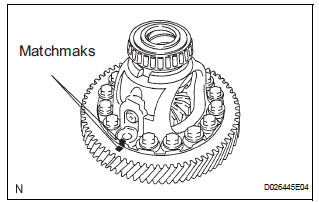
1. REMOVE FRONT DIFFERENTIAL RING GEAR
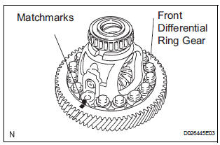
(a) Place matchmarks on the front differential ring gear and differential case.
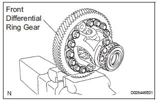
(b) Remove the 14 bolts.
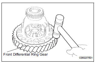
(c) Using a plastic hammer, tap on the front differential ring gear to remove it from the case.
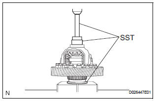
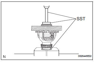
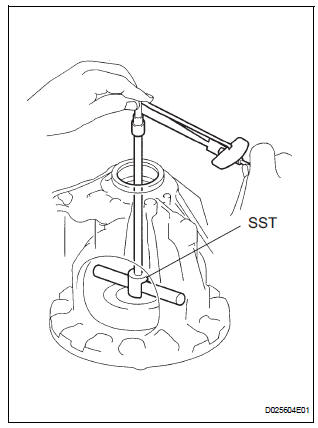
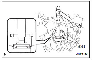
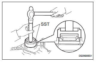
2. REMOVE FRONT DIFFERENTIAL CASE FRONT TAPERED ROLLER BEARING
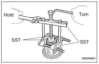
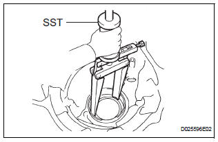
(a) Using SST, remove the front differential case front differential tapered roller bearing from the differential case.
SST 09950-00020, 09950-00030, 09950-60010 (09951-00490), 09950-40011 (09957-04010)
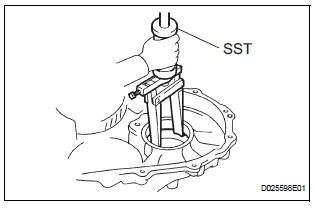
(b) Using SST, remove the front differential case front tapered roller bearing outer race.
SST 09308-00010
3. REMOVE FRONT DIFFERENTIAL CASE REAR TAPERED ROLLER BEARING
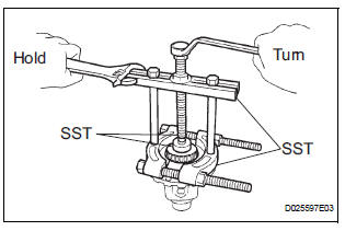
(a) Using SST, remove the front differential case rear tapered roller bearing from the differential case.
SST 09950-00020, 09950-00030, 09950-60010 (09951-00490), 09950-40011 (09957- 04010), 09308-00010
(b) Using SST, remove the front differential case rear tapered roller bearing outer race.
SST 09308-00010
4. REMOVE FRONT DIFFERENTIAL PINION SHAFT STRAIGHT PIN
(a) Using a pin punch and hammer, install the straight pin.
NOTICE: Before removing the straight pin, unstake it with a pin punch.
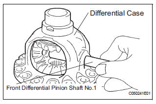
5. REMOVE FRONT DIFFERENTIAL PINION SHAFT NO.1
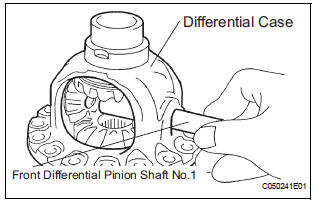
(a) Remove the front differential pinion shaft No.1 from the differential case.
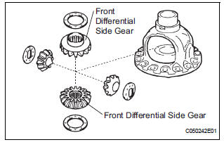
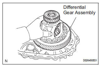
6. REMOVE FRONT DIFFERENTIAL SIDE GEAR
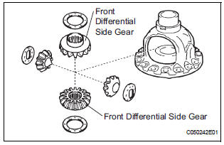
(a) Remove the 2 front differential pinions, 2 pinion thrust washers, 2 front differential side gears and 2 side gear thrust washers from the differential case.
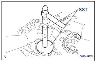
7. REMOVE TRANSAXLE HOUSING OIL SEAL
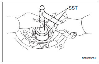
(a) Using SST and a hammer, remove the oil seal.
SST 09950-70010 (09951-07100), 09215-00013 (09215-00471)
8. REMOVE DIFFERENTIAL SIDE BEARING RETAINER OIL SEAL
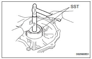
(a) Using SST, remove the oil seal.
SST 09950-70010 (09951-07100), 09608-10010
INSPECTION
1. INSPECT BACKLASH
(a) Using a dial indicator, inspect the backlash of the side gear.
Standard backlash: 0.05 to 0.20 mm (0.0020 to 0.0079 in.)
Thrust washer thickness
Reassembly
1. INSTALL FRONT DIFFERENTIAL SIDE GEAR
(a) Apply ATF to the 2 front differential side gears, 2 side gear thrust washers, 2 front differential pinions and 2 pinion thrust washers and install them to the differential case.
2. INSTALL FRONT DIFFERENTIAL PINION SHAFT NO.1
(a) Coat the front differential pinion shaft No.1 with ATF, and install it to the differential case.
3. INSPECT BACKLASH
HINT: (See page AX-269)
4. INSTALL FRONT DIFFERENTIAL PINION SHAFT STRAIGHT PIN
(a) Using a pin punch and a hammer, install the pinion shaft straight pin.
(b) Using a chisel and a hammer, stake the differential case
NOTICE: Stake the differential case after adjusting the backlash.
5. INSTALL FRONT DIFFERENTIAL CASE FRONT TAPERED ROLLER BEARING
(a) Using SST and a press, install the front differential case front tapered roller bearing to the differential case.
SST 09316-12010, 09550-60010 (09951-00490), 09950-70010 (09951-07100)
NOTICE: Do not damage the bearing cage when installing the bearing inner race.
(b) Using SST and a hammer, install the front differential case tapered roller bearing front outer race to the transaxle housing.
SST 09550-60010 (09951-00490), 09950-60020 (09951-00910)
6. INSTALL FRONT DIFFERENTIAL CASE REAR TAPERED ROLLER BEARING
(a) Using SST and a press, install the front differential case front tapered roller bearing to the differential case.
SST 09316-12010, 09550-60010 (09951-00490), 09950-70010 (09951-07100, 09951-07150)
NOTICE: Do not damage the bearing cage when installing the bearing inner race.
(b) Using SST and a hammer, install the front differential case tapered roller bearing rear outer race to the transaxle housing.
SST 09950-70010 (09951-07100, 09951-07150), 09950-60020 (09951-00890)
NOTICE: No clearance is allowed between the bearing and transaxle housing.
7. ADJUST DIFFERENTIAL SIDE BEARING PRELOAD
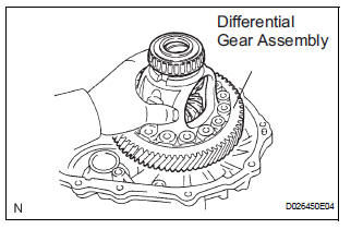
(a) Install the differential assembly to the transaxle case.
(b) Clean the mating surfaces of the transaxle case and transaxle housing.
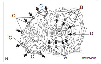
(c) Install the transaxle housing to the transaxle case and tighten them with the 16 bolts.
Torque: Bolt A 25 N*m (255 kgf*cm, 18 ft.*lbf) Bolt B 33 N*m (337 kgf*cm, 24 ft.*lbf) Bolt C 29 N*m (295 kgf*cm, 21 ft.*lbf) Bolt D 22 N*m (226 kgf*cm, 16.0 ft.*lbf)
HINT:
Apply seal packing or equivalent to bolts A and D.
Seal packing: THREE BOND 2403 or equivalent Bolt length: Bolt A: 50 mm (1.969 in.) Bolt B: 50 mm (1.969 in.) Bolt C:
42 mm (1.654 in.) Bolt D: 72 mm (2.835 in.)
HINT: Usually, bolt A is non-reusable. In this case, however, the bolt can be used after cleaning it.
(d) Using SST, turn the differential assembly to the right and left 2 or 3 times to settle the bearing.
SST 09564-32011
(e) Using SST and a torque wrench, measure the turning torque of the differential.
SST 09564-32011 Turning torque at 60 rpm: New bearing: 0.20 to 0.69 N*m (2.0 to 7.0 kgf*cm, 1.8 to 6.1 in.*lbf) Used bearing: 0.10 to 0.35 N*m (1.0 to 3.6 kgf*cm, 0.9 to 3.1 in.*lbf)
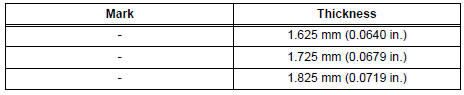
HINT: If the turning torque is not as specified, refer to the table below to select a thrust washer so that the specified value is achieved.
Flange thickness: mm (in.)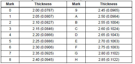
(f) Remove the 16 bolts and the transaxle housing.
8. INSTALL FRONT DIFFERENTIAL RING GEAR
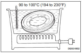
(a) Using ATF and heater, heat the front differential ring gear to 90 to 110°C (194.0 to 230.0°F).
NOTICE: Do not heat the ring gear to more than 110°C (230.0°F).
(b) Clean the contact surface of the front differential case.
(c) Align the matchmarks, and install the front differential ring gear case quickly.
NOTICE: Do not install the bolts while the ring gear is hot.
(d) Tighten the 14 bolts.
Torque: 95.0 N*m (970 kgf*cm, 70 ft.*lbf)
NOTICE: Tighten the bolts a little at a time in a diagonal pattern.
9. INSTALL TRANSAXLE HOUSING OIL SEAL
(a) Using SST and a hammer, install a new oil seal.
SST 09223-15020, 09950-70010 (09951-07150)
(b) Coat the lip of oil seal with a little MP grease.
Oil seal installation depth: 0 +- 0.5 mm (0 +- 0.0197 in.)
10. INSTALL DIFFERENTIAL SIDE BEARING RETAINER OIL SEAL
(a) Using SST and a hammer, install a new oil seal.
SST 09710-30050, 09950-70010 (09951-07150)
(b) Coat the lip of the oil seal with a little MP grease.
Oil seal installation depth: 0 +- 0.5 mm (0 +- 0.0197 in.)
 Differential case
COMPONENTS
...
 Speed sensor
Components
...
Other materials:
Installation
1. INSTALL SLIDE DOOR ROLLER ASSEMBLY UPPER
Apply MP grease to the rotating areas of the roller.
Install the roller with the 2 bolts.
Torque: 13 N*m (130 kgf*cm, 10 ft.*lbf)
2. INSTALL SLIDE DOOR HINGE ASSEMBLY CENTER LH
Apply MP grease to the rotating areas of the hinge.
In ...
Installation
1. INSTALL ENGINE OIL COOLER
(a) Clean the oil cooler contact surface on the cooler
mounting.
(b) Install a new O-ring to the oil cooler.
(c) Install the oil cooler assembly with the union bolt.
Torque: 68 N*m (693 kgf*cm, 50 ft.*lbf)
Install the 2 water by-pass hoses with the bolt ...
Short to GND in Side Squib RH Circuit
DTC B0112/41 Short to GND in Side Squib RH Circuit
DESCRIPTION
The side squib RH circuit consists of the center airbag sensor assembly and
the front seat side airbag
assembly RH.
The circuit instructs the SRS to deploy when deployment conditions are met.
DTC B0112/41 is recorded when a sh ...
