Toyota Sienna Service Manual: Disassembly
1. REMOVE PROPELLER SHAFT ASSEMBLY
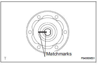
(a) Put matchmarks on both the flanges.
(b) Remove the 4 nuts, bolts and washers.
2. REMOVE INTERMEDIATE SHAFT
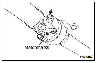
(a) Put matchmarks on the propeller shaft subassembly and universal joint flange.
NOTICE: Do not use a punch for the marks.
(b) Using a hexagon wrench (6 mm), remove the 6 bolts and 2 washers and separate the intermediate shaft from the propeller shaft assembly rear.
3. REMOVE CENTER SUPPORT BEARING ASSEMBLY NO.1
(a) Using a chisel and a hammer, loosen the staked part of the nut.
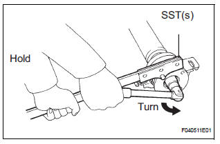
(b) Using SST(s) to hold the front flange, remove the nut and plate washer.
SST 09330-00021
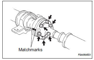
(c) Put matchmarks on the rear flange and shaft.
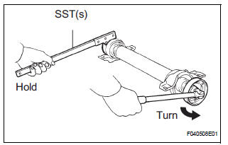
(d) Hold the intermediate shaft in a vise between aluminium plates.
NOTICE: Do not overtighten the vise
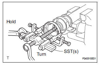
(e) Using SST(s), remove the rear flange.
SST 09950-40011 (09951-04020, 09952-04010, 09953-04030, 09954-04010, 09955-04061, 09957-04010, 09958-04011)
NOTICE: Be careful not to damage the universal joint flange.
(f) Remove the center support bearing assembly No. 1 (rear) and washer.
4. REMOVE CENTER SUPPORT BEARING ASSEMBLY NO.1
(a) Using a chisel and a hammer, loosen the staked part of the nut.
(b) Using SST(s) to hold the front flange, remove the nut and plate washer.
SST 09330-00021
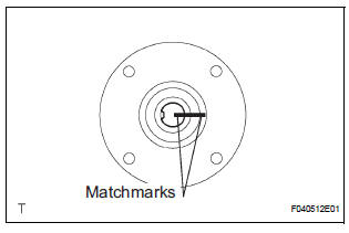
(c) Put matchmarks on the front flange and shaft.
(d) Hold the intermediate shaft in a vise between aluminium plates.
NOTICE: Do not overtighten the vise.
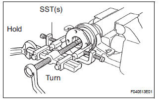
(e) Using SST(s), remove the front flange.
SST 09950-40011 (09951-04020, 09952-04010, 09953-04030, 09954-04010, 09955-04061, 09957-04010, 09958-04011)
NOTICE: Be careful not to damage the universal joint flange.
(f) Remove the center support bearing assembly No. 1 (front) and washer.
 Removal
1. REMOVE EXHAUST PIPE ASSEMBLY
(a) Remove exhaust pipe assembly (See page EX-8).
2. REMOVE PROPELLER W/CENTER BEARING SHAFT ASSEMBLY
(a) Depress the brake pedal and hold it down.
(b) Using ...
 Inspection
1. INSPECT SPIDER BEARING
(a) Check that the spider bearing moves smoothly by
turning the flange.
(b) Check for the looseness around the joint by strongly
moving the flange in the axial and ...
Other materials:
Reassembly
1. INSTALL CENTER SUPPORT BEARING ASSEMBLY NO.1
(a) Set the center support bearing assembly No. 1
(front) to the intermediate shaft, as shown in the
illustration.
(b) Install a new washer to the intermediate shaft.
NOTICE:
Be sure to install the bearing in the correct
direction.
(c ...
Installation
1. INSTALL VANE PUMP ASSEMBLY
(a) Temporarily install the bolt to the vane pump
assembly.
(b) Install the vane pump assembly.
(c) Temporarily install the bolt (B).
(d) Using SST, tighten the 2 bolts.
SST 09249-63010
Torque:Without SST
43 N*m (439 kgf*cm, 32 ft.*lbf)
With SST
29 ...
How to proceed with
troubleshooting
HINT:
Troubleshooting of the wireless door lock control system is
based on the premise that the power door lock system, the
power slide door system, the power back door system and
the power window system are operating normally.
Therefore, before troubleshooting the wireless door lo ...
