Toyota Sienna Service Manual: Disassembly
1. SEPARATE REAR DRIVE SHAFT INBOARD JOINT BOOT CLAMP
(a) Using a screwdriver, remove the 2 rear drive shaft inboard joint boot clamps as shown in the illustration.
2. SEPARATE REAR DRIVE SHAFT INBOARD JOINT BOOT
(a) Separate the rear drive shaft inboard joint boot from the inboard joint assembly.
3. REMOVE REAR DRIVE SHAFT INBOARD JOINT ASSEMBLY
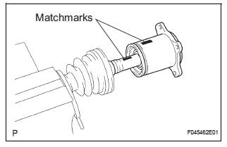
(a) Put matchmarks on the inboard joint assembly and outboard joint shaft.
NOTICE: Do not use a punch for the marks.
(b) Pull out the inboard joint assembly.
NOTICE: Be careful not to drop the balls.
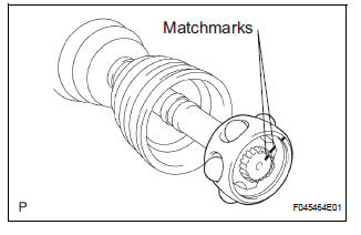
(c) Place matchmarks on the outboard joint shaft, inner race and cage.
NOTICE: Do not punch the marks.
(d) Remove the 6 bolts.
(e) Slide the cage toward outboard joint.
(f) Using a snap ring expander, remove the snap ring.
(g) Using a brass bar and hammer, remove the inner race.
(h) Remove the cage.
(i) Remove the inboard joint boot, inboard joint boot clamp and inboard joint boot No. 2 clamp.
4. REMOVE REAR DRIVE SHAFT OUTBOARD JOINT BOOT CLAMP
(a) Using pliers, remove the 2 rear drive shaft outboard joint boot clamps as shown in the illustration.
5. REMOVE REAR DRIVE SHAFT OUTBOARD JOINT BOOT
(a) Remove the outboard joint boot from the outboard joint shaft.
(b) Remove the old grease from the outboard joint.
NOTICE: Do not disassemble the outboard joint.
 Removal
1. REMOVE REAR WHEEL
2. REMOVE TAIL EXHAUST PIPE ASSEMBLY (See page
EX-8)
3. SEPARATE REAR SPEED SENSOR
(a) Remove the bolt and the speed sensor from the
axle carrier.
NOTICE:
Be careful not ...
 Inspection
1. INSPECT REAR DRIVE SHAFT ASSEMBLY LH
(a) Check that there is no remarkable play in the radial
direction of the outboard joint.
(b) Check that the inboard joint slides smoothly in the
thru ...
Other materials:
Charge Warning Light Comes ON while Driving
INSPECTION PROCEDURE
1 CHECK LOCK FUNCTION OF CLUTCH PULLEY
(a) Check the lock function with the pulley installed in the
vehicle.
(1) Visually check that the rotor in the generator
operates with the engine started.
(b) Check the lock function with the pulley removed from the
vehicle.
( ...
Sleep Operation Failure of Occupant Classification
ECU
DTC B1796 Sleep Operation Failure of Occupant Classification
ECU
DESCRIPTION
During sleep mode, the occupant classification ECU reads the condition of
each sensor while the ignition
switch is off.
In this mode, if the occupant classification ECU detects an internal
malfunction, DTC B1796 ...
Removal
NOTICE:
When installing, coat the parts indicated by the arrows
with power steering fluid or molybdenum disulfide
lithium base grease (See page PS-21).
1. INSPECT CENTER FRONT WHEEL
2. REMOVE FRONT WHEEL
3. SEPARATE TIE ROD ASSEMBLY LH
SST 09628-62011
4. SEPARATE TIE ROD ASSEMBLY RH
SST 096 ...
