Toyota Sienna Service Manual: Display Signal Circuit between Radio and Navigation Assembly and Television Camera Assembly
DESCRIPTION
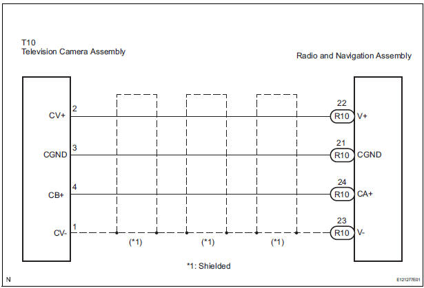
This is the display signal circuit of the television camera assembly.
WIRING DIAGRAM
INSPECTION PROCEDURE
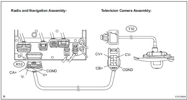
1 CHECK HARNESS AND CONNECTOR (RADIO AND NAVIGATION ASSEMBLY - TELEVISION CAMERA ASSEMBLY)
- Disconnect the R10 connector from the radio and navigation assembly.
- Disconnect the T10 connector from the television camera assembly.
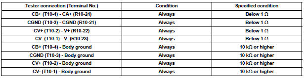
- Measure the resistance according to the value(s) in the table below.
Standard resistance
2 INSPECT RADIO AND NAVIGATION ASSEMBLY
- Reconnect the radio and navigation assembly R10 connector.
- Measure the voltage according to the value(s) in the table below
Standard voltage

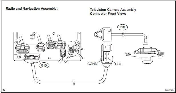
3 INSPECT TELEVISION CAMERA ASSEMBLY
- Reconnect the radio and navigation assembly R10 connector and the television camera assembly T10 connector.

- Check the waveform of the television camera assembly using an oscilloscope.
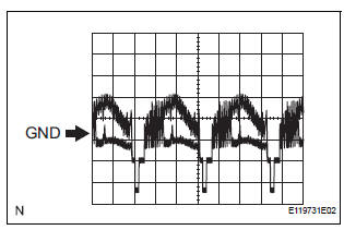
- Measurement terminal: CV+ - CVMeasurement setting: 0.2 V/DIV, 0.2 μs/DIV Condition: Ignition switch ON, Shift lever in R range
OK: Pulses as shown in the illustration.
PROCEED TO NEXT CIRCUIT INSPECTION SHOWN IN PROBLEM SYMPTOMS TABLE
 Reverse Signal Circuit
DESCRIPTION
The radio and navigation assembly receives a reverse signal from the
park/neutral position switch.
WIRING DIAGRAM
INSPECTION PROCEDURE
1 INSPECT RADIO AND NAVIGATION ASSEMBLY
...
 Clearance warning ECU
COMPONENTS
REMOVAL
1. REMOVE FRONT DOOR SCUFF PLATE LH
2. REMOVE COWL SIDE TRIM BOARD LH
3. REMOVE INSTRUMENT PANEL FINISH PANEL SUBASSEMBLY LOWER LH
4. REMOVE NO. 1 INSTRUMENT PANEL SAFETY PAD ...
Other materials:
Reassembly
1. INSTALL FRONT SEAT CUSHION SHIELD LOWER LH
Install the front seat cushion shield lower LH.
2. INSTALL FRONT SEAT CUSHION SHIELD LOWER
RH
3. INSTALL RECLINING ADJUSTER INSIDE COVER LH
Install the reclining adjuster inside cover LH (upper)
with the screw.
4. INSTALL RE ...
Installation
1. INSTALL TIRE PRESSURE WARNING ECU
(a) Connect the connector to the tire pressure warning
ECU.
(b) Install the tire pressure warning ECU with the screw.
2. INSTALL INSTRUMENT PANEL SAFETY PAD SUBASSEMBLY
HINT:
Refer to the instructions for INSTALLATION of the
instrument panel safety ...
On-vehicle inspection
1. INSPECT SIDE AIRBAG SENSOR (VEHICLE NOT
INVOLVED IN COLLISION)
Perform a diagnostic system check.
2. INSPECT SIDE AIRBAG SENSOR (VEHICLE
INVOLVED IN COLLISION AND AIRBAG HAS NOT
DEPLOYED)
Perform a diagnostic system check.
When the center pillar of the vehicle or ...
