Toyota Sienna Service Manual: Display Signal Circuit between Television Display Assembly and Radio and Navigation Assembly
DESCRIPTION
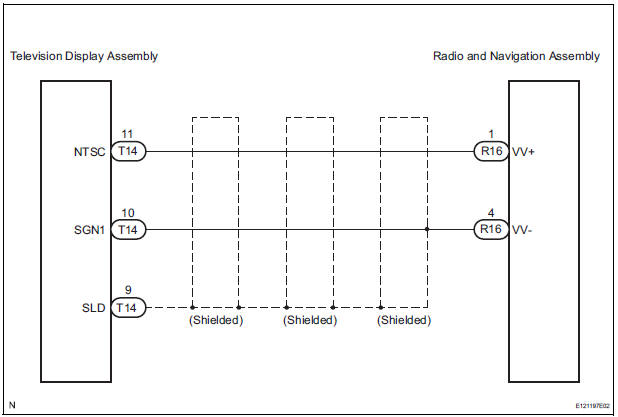
This circuit sends a DVD image signal from the television display assembly to the radio and navigation assembly.
WIRING DIAGRAM
INSPECTION PROCEDURE
1 CHECK HARNESS AND CONNECTOR (RADIO AND NAVIGATION ASSEMBLY - TELEVISION DISPLAY ASSEMBLY)
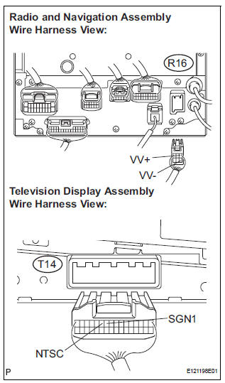
- Disconnect the radio and navigation assembly connector R16 and television display assembly connector T14.
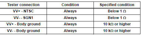
- Measure the resistance according to the value(s) in the table below.
Standard resistance
2 INSPECT TELEVISION DISPLAY ASSEMBLY
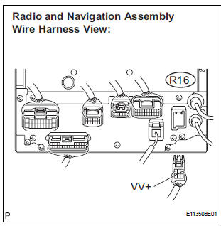
- Reconnect the television display assembly connector R16.
- Measure the waveform according to the table below.
OK
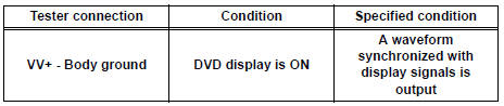
HINT: The waveform pattern may differ from that shown in the illustration below due to differences in oscilloscope setting. A normal television display assembly operating condition can be determined if any waveform is output.
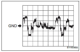
- Oscilloscope waveform
- Terminal: VV+ - Body groun
Setting: 200 mV/DIV., 10 μs/DIV.
Condition: DVD display is ON.
PROCEED TO NEXT CIRCUIT INSPECTION SHOWN IN PROBLEM SYMPTOMS TABLE
 Navigation Voice Circuit
DESCRIPTION
This circuit is used when the voice guidance in the navigation system is on.
WIRING DIAGRAM
INSPECTION PROCEDURE
1 CHECK HARNESS AND CONNECTOR (RADIO AND NAVIGATION ASSEMBLY - STER ...
 Microphone Circuit between Microphone and Radio and Navigation
Assembly
Microphone Circuit between Microphone and Radio and Navigation
Assembly
DESCRIPTION
This circuit sends a microphone signal from the microphone to the radio and
navigation assembly.
It also supplies power from the radio and navigation assembly to the microphone.
WIR ...
Other materials:
Inspection
1. INSPECT WINDSHIELD WIPER MOTOR ASSEMBLY
LO Operation Check
Connect the battery (+) to the terminal 1 (+1) of
the connector, the battery (-) to the terminal 5
(E) of the connector, and check that the motor
operates at low speed (LO).
HI Operation Check
...
Mute Signal Circuit between Radio Receiver and Television Display
Assembly
DESCRIPTION
The radio receiver controls the volume according to the MUTE signal from the
television display
assembly.
The MUTE signal is sent to reduce noise and a popping sound generated when
switching the mode, etc.
If there is an open in the circuit, noise can be heard from the speake ...
Diagnosis system
1. CHECK DLC3
The vehicle's ECU uses ISO 15765-4 for
communication protocol. The terminal arrangement
of the DLC3 complies with SAE J1962 and matches
the ISO 15765-4 format.
NOTICE:
*: Before measuring the resistance, leave the
vehicle as is for at least 1 minute and do not
...
